I have several pairs of old WW2 headphones all with the same diaphragm ,this was pretty universal at the time old Bakelite UK 100 type/200 type /300 type telephones had the same diaphragm as well as other equipment .
They were specified over a set audio range --no not--20KHz more like under 10KHz and designed for that as were the magnets .Headphone impedance's varied and the steel disc wasn't just ordinary steel.
A planar acoustic transducer has a built in coil whereas the diaphragm in the headphones moves in sympathy with the magnetic coils variance of output directed at a steel disc which is flattened against the coils by magnetism --always move the disc SIDEWAYS don't just rip it off .
If you want to use a planar diaphragm it requires precisely placed magnets designed to work with it.
Nothing wrong with your theory just the engineering design implementation to get it working correctly which will not be with the original setup so you would be making faux old headphones that outwardly look the part but nothing remains inside that is original.
Thanks Duncan! That's useful.
I have my Dad's 1950s crystal set for comparison and they are very similar. It's quite surprising how the basic design seems little changed over the 40 years between them, despite the emergence of amplification, development of speakers, the headphone boom of the 1920s, the buildup of military technology prior to and during WW2 etc.
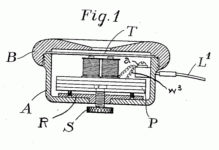
This specific model of headphones actually has a mechanism to change the seperation between the pole-pieces and the diaphram (the screw in the diagram below), so it might be more flexible in adapting to a different diaphram.


(from the attached patent doc)
I have my Dad's 1950s crystal set for comparison and they are very similar. It's quite surprising how the basic design seems little changed over the 40 years between them, despite the emergence of amplification, development of speakers, the headphone boom of the 1920s, the buildup of military technology prior to and during WW2 etc.
This specific model of headphones actually has a mechanism to change the seperation between the pole-pieces and the diaphram (the screw in the diagram below), so it might be more flexible in adapting to a different diaphram.


(from the attached patent doc)
Attachments
While "sensitivity" is quoted as the reason for the adjusting screw (S) it also provided a means of altering --slightly-- the FR-frequency response , reducing slightly the higher frequency transmission some people actually liked a "smooth " sound in those days , just look at an old tube radio.s "tone control " .
Its a "top -cut " type placing a capacitor across the primary of the single ended output transformer .
I can quote direct from a Wireless reviewer in a 1930,s addition of Wireless World -
"adjusting the tone control brought about a beautifully ---Mellow reproduction of the music rendering it a joy to listen to " ---of course it would those top cut controls were harsh you would be lucky to get much over 1KHZ when using it.
It wasn't till later that full frequency range --in those days 15KHZ was designed into equipment and better designed output transformers.
Regarding the diaphram, my guess is that it is Stalloy (3% silicon, now called ferrosilicon) as described here https://royalsocietypublishing.org/doi/pdf/10.1098/rspa.1908.0049
If I could find small, thin sheets of modern ferrosilicon or silicon steel, they might be good candidates to make new diaphrams with minimal changes from the original design. Where would I obtain such sheets?
If I could find small, thin sheets of modern ferrosilicon or silicon steel, they might be good candidates to make new diaphrams with minimal changes from the original design. Where would I obtain such sheets?
I’ve got several sets of similar technology headphones with manufactured dates from early 20th century to the early 1970s. I think that a uniformly thinner diaphragm might be crumpled or adversely cupped inward too much by the magnet, and would also have less material for the varying magnetic field to act on. It’d be interesting to see if you could get some appropriate new material (so as not to risk trashing the original and then selectively mask and acid or electrically etch so that you had “original equipment” thickness around the perimeter and directly over the coils, but thinned out everywhere in between. US government mil-spec headphones, using this technology, new old stock and still sealed in packaging, have shown up on eBay even over the last few years, if you wanted a less vintage platform to risk adverse outcomes with.
Regarding the diaphram, my guess is that it is Stalloy (3% silicon, now called ferrosilicon) as described here https://royalsocietypublishing.org/doi/pdf/10.1098/rspa.1908.0049
If I could find small, thin sheets of modern ferrosilicon or silicon steel, they might be good candidates to make new diaphrams with minimal changes from the original design. Where would I obtain such sheets?
I suspect for diaphragm use such metals need to be heat-treated into a hardened condition so they are properly springy - not all electrical (silicon) steels may work for this. You could just use spring-steel sheet of course.
I would agree with Mark up to his last sentence-- "you could just use spring-steel".
I removed the diaphragm from my genuine original GPO candlestick telephone , the insert is stamped =25 with a very pale green coating to stop it rusting .
By itself it is "non-magnetic " -note I said -by itself it contains the correct amount of carbon/iron to react correctly to the varying lines of force transmitted by the wound coils round the magnet.
It is hardened to a certain degree and I think its about 50"thou " thick-i don't have my micrometer to hand , it must be the correct balance of metals to get this right and provide the correct hysteresis for clear transmission of speech.
Percentages of the composition are laid out on the web.
I will try and find my very old GPO technical handbook as the small book forms only contain old school telephone circuits .
Yes I recognise the term Stalloy
- Home
- Amplifiers
- Headphone Systems
- Antique headphones with moving iron drivers


