OK, great! Thanks  Am relieved that they're a lot closer than I was worried they might be.
Wish I was quicker getting my part done -- still working.
Have you had a chance to check out LT Spice? It's a heck of a thing to be available free! But the learning curve can require some patience. Maybe try not to do the dumb thing I did and overlook the many examples that come with. Fiddling those is a lot better place to start than going straight into building expertise in schematic entry.
Am relieved that they're a lot closer than I was worried they might be.Wish I was quicker getting my part done -- still working.
Have you had a chance to check out LT Spice? It's a heck of a thing to be available free! But the learning curve can require some patience. Maybe try not to do the dumb thing I did and overlook the many examples that come with. Fiddling those is a lot better place to start than going straight into building expertise in schematic entry.
Last edited:
Wow -- a 17-month-old! That is such an adorable age, but boy can I imagine limited free time -- pretty sure I didn't have 10 or 15 hobby minutes a month for the whole first 3 or 4 years! Nothing but baths, bottle making, diaper changes and laundry, laundry, laundry ..
Cheers
That is such an adorable age, but boy can I imagine limited free time -- pretty sure I didn't have 10 or 15 hobby minutes a month for the whole first 3 or 4 years! Nothing but baths, bottle making, diaper changes and laundry, laundry, laundry ..Cheers
Last edited:
Hey gregas,
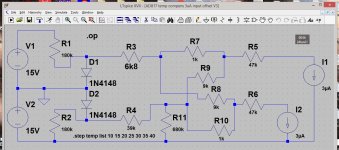
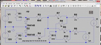
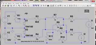
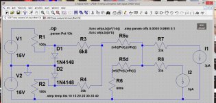
Guess I better go ahead and post these -- maybe some of the much-sharper-than-me folks on here will see the flaw in my thinking. I've been going around in circles for hours now, fixing one shortfall but causing another, can't remember what the original *supposed clever insight* was, and still haven't yet gotten to what was supposed to have been the *real point* of the exercise -- letting the simulator push the pencil!
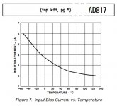
What seemed like an obvious, simple exercise to simulate the AD817's decreasing input current with increasing temperature -- 3,75uA at 0 C to 2,75uA at 40 C -- and simplifying to linear over that range -- has not revealed itself to me, short of building a model. Of course that would be a worthwhile pursuit. But not something I'm capable of doing on a short timescale. Maybe someone on here knows how to implement a table of temp:current value-pairs for one of LT Spice's built-in current sources, but I haven't found a way to do that, either.
There ARE numerous, popular, nominally uncomplicated solutions to remedy this issue. But they'd require additional op-amps or other active circuitry -- nothing so simple as a diode and a few resistors.
Best practical suggestion would be to use it as is, adjusted for your typical ambient temperatures according to the season. Then be sure to have the headphones unplugged at power-up and power-down.
Or cave, at least temporarily, and fit the output coupling capacitor suggested by other members (which offers the best protection for the headphones, too).
Sorry for the limited joy,
Cheers
Guess I better go ahead and post these -- maybe some of the much-sharper-than-me folks on here will see the flaw in my thinking.
I've been going around in circles for hours now, fixing one shortfall but causing another, can't remember what the original *supposed clever insight* was, and still haven't yet gotten to what was supposed to have been the *real point* of the exercise -- letting the simulator push the pencil!What seemed like an obvious, simple exercise to simulate the AD817's decreasing input current with increasing temperature -- 3,75uA at 0 C to 2,75uA at 40 C -- and simplifying to linear over that range -- has not revealed itself to me, short of building a model. Of course that would be a worthwhile pursuit. But not something I'm capable of doing on a short timescale. Maybe someone on here knows how to implement a table of temp:current value-pairs for one of LT Spice's built-in current sources, but I haven't found a way to do that, either.
There ARE numerous, popular, nominally uncomplicated solutions to remedy this issue. But they'd require additional op-amps or other active circuitry -- nothing so simple as a diode and a few resistors.
Best practical suggestion would be to use it as is, adjusted for your typical ambient temperatures according to the season. Then be sure to have the headphones unplugged at power-up and power-down.
Or cave, at least temporarily, and fit the output coupling capacitor suggested by other members (which offers the best protection for the headphones, too).
Sorry for the limited joy,
Cheers
Attachments
Last edited:
Hey Rick
Thanks for all your help with this project.
I was hoping there was a simple fix to get our temp compensation circuit to behave.
Not sure if anyone else will chime in here.
It's been you and me for a while now.
So if I'm to adjust with the current setup for dc offset.
I let it warm up and adjust for lowest dc voltage on both channels.
What is considered ok? At what point would it not be ok? Possible damage to headphones?
You're very welcome!
I don't have a good answer for 'how much is too much', especially for 'modern' headphones. Probably something in the 10 to 15 mV range should not cause trouble.
As for the procedure ..
- headphones unplugged
- cover on but unfastened, unit in normal operating orientation
- warm-up for 6 to 8 minutes
- attach the DMM black probe to headphone ground
- remove the cover, flip unit if necessary, make a quick adjustment -- less than 1 minute
- replace the cover, wait another 2 or 3 minutes, repeat for other channel
We'll want to aim for a setting that produces lowest maximum value, of the greater of the two absolute values. If one channel is +12mV, for example, and the other is -5mV, turn the trimpot CCW until their absolute values approximately match.
I'd say if it isn't possible to get both channels less than about |25|mV, a large electrolytic might be a wise temporary precaution -- especially if your headphones are expensive. If the caps end up retired sometime later, and your electronics hobby continues, you might be surprised how handy a couple of 1000uF/35V capacitors lying about can be.
Am still working on 'the problem', by the way -- but it'll probably be a couple/few weeks before there's any joy.
Regards
Last edited:
It's the voltage drop across the input resistor. The AD817 is designed for video service -- bandwidth and linearity extending into the low 2-digit MHz. This calls for much lower impedances than audio; 75 and 150 ohms are common. At those impedances the 3uA current that the '817 requires isn't an issue; at the 10k to 50k ohms typical of consumer audio gear, that causes a 30 to 150mV offset.
Of course, we could make the 68k's smaller. But it would have to be objectionably low -- 3 - 5k ohms -- to get the offset down to the 9 to 15mV range. That would load the preamp too heavily.
Sometime in looking over the spec PDF, I noticed the input current's declining slope with rising temperature. (see below -- haven't yet sorted how to get the thumbnail to turn up mid-text)
Then, cobbling up the arithmetic mentally, I thought, 'Maybe we could balance it against that of a diode and approximately cancel it!' I still have no idea what I botched in the reasoningo), but I'm not ready to throw in the towel just yet.
Glad you're willing to concede and install the caps, though, even if (hopefuly) only temporarily. Much safer for the 'phones.
Of course, we could make the 68k's smaller. But it would have to be objectionably low -- 3 - 5k ohms -- to get the offset down to the 9 to 15mV range. That would load the preamp too heavily.
Sometime in looking over the spec PDF, I noticed the input current's declining slope with rising temperature. (see below -- haven't yet sorted how to get the thumbnail to turn up mid-text
)Then, cobbling up the arithmetic mentally, I thought, 'Maybe we could balance it against that of a diode and approximately cancel it!' I still have no idea what I botched in the reasoning
o), but I'm not ready to throw in the towel just yet.Glad you're willing to concede and install the caps, though, even if (hopefuly) only temporarily. Much safer for the 'phones.
Attachments
You surely could .. are you that tight on space?
Keeping the Temp Compensation won't impair performance. Since you're fitting bi- or non-polars there's no advantage with or without.
I'm still operating on the expectation that finding my way through the thicket of interactive factors may still happen.
Keeping the Temp Compensation won't impair performance. Since you're fitting bi- or non-polars there's no advantage with or without.
I'm still operating on the expectation that finding my way through the thicket of interactive factors may still happen.
Last edited:
Hey rick
Hopefully your making your way through the thicket, and haven't lost your way.
I've been reading over some of the older posts here. In post #28 JP mentioned to fix an issue affecting the amps ability to play the full audio spectrum. One issue was the shared input cap between tube section and the HPA. It wasn't large enough for the shared duty. we fixed that by giving the HPA it's own coupling cap. (I used a 22uf electrolytic. He mentioned the 100k input resistance being too high. I removed that 100k resistor going to ground. Your circuit hast two 68k resistors(post 67) going to the inputs of the chip. Is there still any issue with regard to being able to play bass? I put 68k and 22uf into RC Low pass filter calculator and get .1Hz that doesn't seem right?
Hope you meant High Pass Filter Calculator.
That is lower than it needs to be, but IIRC it was what you had on hand. And at the time we weren't sure what the eventual solution to input biasing would be. It can certainly be smaller if you want. Maybe use the Filter Calculator to find a value that you like better.
Or maybe wait to see what further dust settles concerning the input bias circuit.
The bass deficiency would have been due to too small of a coupling capacitor value, not too large. I trust it has sufficient bass presently.
Also, maybe a good time to mention -- the 22uF input coupling cap must come from the wiper of the volume control -- not the valve side of IT's coupling cap.
Hey Rick
Thanks for the response. Yes I'm taking the input signal from the volume control.
Recently I recapped and NAD preamp. I was comparing it to my tube preamp. Then NAD sounds more detailed and better imagining. So I was just exploring if there was any particular reason for that?
Thanks for the response. Yes I'm taking the input signal from the volume control.
Recently I recapped and NAD preamp. I was comparing it to my tube preamp. Then NAD sounds more detailed and better imagining. So I was just exploring if there was any particular reason for that?
You surely could .. are you that tight on space?
Keeping the Temp Compensation won't impair performance. Since you're fitting bi- or non-polars there's no advantage with or without.
I'm still operating on the expectation that finding my way through the thicket of interactive factors may still happen.
Hey Rick,
It's been a few weeks since I last posted here.
Id like to finish up my preanp and move on to my power amps.
Have you had a chance to futher look into the headphone amp offset voltage issue?
- Home
- Amplifiers
- Headphone Systems
- help with op amp headphone amp hum and distortion