[ New thread split from here - tube preamp makes rushing noise at speakers]
Hey guys,
So the muting relay works great and the amp sounds good.
There's no hum or noise now.
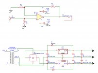
So now to sort out the headphone amp. Perhaps someone has some suggestions. Right now there's a pretty loud hum in the headphones and the amp sounds distorted. Here's the schematic. The hum may be due to layout. The circuit board and input wires for the headphone amp are close to the transformer. I'm going to change the input wire to shielded cable. Hopefully that works.
New thread split from here - tube preamp makes rushing noise at speakers]Hey guys,
So the muting relay works great and the amp sounds good.
There's no hum or noise now.
So now to sort out the headphone amp. Perhaps someone has some suggestions. Right now there's a pretty loud hum in the headphones and the amp sounds distorted. Here's the schematic. The hum may be due to layout. The circuit board and input wires for the headphone amp are close to the transformer. I'm going to change the input wire to shielded cable. Hopefully that works.
Attachments
The circuit board and input wires for the headphone amp are close to the transformer. First correct that. No sensitive circuit should be close to a mains transformer (steel chassis no doubt) unless this is a special type with extreme low stray field.
I already tried to make it clear but it really would do yourself and any one else a service if you would first think, design and then build. It is not advisable to develop the habit to "just do something" and then ask forum members how to solve stuff. This habit is very hard to get rid of and there is some laziness in it which is not a virtue. This is a constructive comment as it would save everyone time. In this case you gave the answer yourself so please solve it.
The circuit itself is a very basic textbook circuit. You omitted input caps and output caps (depending on which opamp is used) and muting. C2 and C5 should be 1000 µF as a minimum and CLC/CRC would be even better. Most things in power supplies are shared no matter if you use tubes or semis. A DC PSU should give a straight line on your oscilloscope so no ripple and as least noise as possible. Volume control is lacking (your ears will thank me) and gain seems too high but that is liked among tube people. In other words, you should have first thought, then designed and then build. Sorry.
* Since this is a thread about a tube preamp making noises I would like to advise to make a new thread in the solid state section regarding the opamp circuit. Or in the (new to me) "Headphone Systems" section. Make sure to study other standard opamp HPA circuits first and compare with yours and add what is lacking. Make sure to add a type number for the opamp you use as that is relevant info.
Last edited:
Hey guys,
So now to sort out the headphone amp. Perhaps someone has some suggestions. Right now there's a pretty loud hum in the headphones and the amp sounds distorted.
Have you earthed the zero volt line ?
I have an amplifier test bed that has a MP3 input and without an earth the hum is terrible. As soon as I clip on scope probe to ground it goes dead silent.
jean-paul...really?
The purpose of forums like this (my opinion) is to help others to learn. I see no need to criticize someone with less knowledge that is wanting to learn that is struggling.
Yes but then first design, draw a schematic, then ask questions, get replies, show a picture of the location where it will be situated, ask questions, get replies and then build. I think that way of working is way more effective for learning and gaining experience but please correct me if I am wrong. I am certainly NOT criticizing someone with less knowledge (why would I help out otherwise? I solved a few issues already) and I really don't see where I gave that impression. I am pointing at an ineffective/inefficient way of working that is mostly at the expense of the OP but also costs other peoples time.
Being even more direct: we now see a bog standard circuit with omitted parts being already built at the wrong location. There would have been gain in a different way of working. Also all information should be given straight away, a complete schematic and some pictures would help. Now the people that help out must ask many questions and they need to assume things which often goes wrong, this thread being a good example. The schematic indicates that there is no volume control and although assumption is quickly done we know this is impossible. No input and output caps indicate a source with DC offset will result in amplified DC and possibly fried head phones.... When the schematic had been shown before the actual building both OP and us had saved time and issues.
This is all in the interest of the OP!
@gregas: please report your own post #201 and ask the mods to cut from post #201 onwards to a new thread in the right section with a title like "Help wanted with my HPA" or the like.
Last edited:
Hey guys,
So the muting relay works great and the amp sounds good.
There's no hum or noise now.
Can you or someone else point me to the specific post that solves the original noise problem since this thread has over 20 pages? I see a lot of posts about relay and muting circuits but I just want to locate the one post about finding the culprit and solving the noise issue as a friend's preamp has similar noise. What caused the noise? Sorry, I tried to go back previous posts to look for it to no avail. Thank you in advance.
PS, Why is the input cathode follower even necessary? Since the preamp has little gain, wouldn't it be easier just to have a split-load/cathodyne/concertina circuit and cap couple to the two FETs to get a balance circuit?
Last edited:
Hey guys,
Thanks for all the responses. I built the headphone section a year ago along with the tube preamp.
We decided to sort out the issues with the preamp before we worried about the headphone amp. The preamp is working well now. The circuit was completely changed. I longer have the 250v veroboard with the mosfets.
So now to worry about the headphone amp.
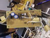
I will post a picture of the chassis with all the parts so you guys can visualize what's going on. I took a look at the marking on the chips for the headphone amp AD817AN.
JP.
The chassis is aluminum. I don't want to move the transformer unless absolutely necessary. As you can imagine, It would be a lot of work to do so.
Did you mean both c2/3 should all be min 1000uf? I have 1000uf caps for position c2/3 but only 10uf for position c4/5
There is a volume control. It also works of the bipolar power supply. VCU | academyaudio
Nigel yes the 0v is grounded.
Thanks for all the responses. I built the headphone section a year ago along with the tube preamp.
We decided to sort out the issues with the preamp before we worried about the headphone amp. The preamp is working well now. The circuit was completely changed. I longer have the 250v veroboard with the mosfets.
So now to worry about the headphone amp.
I will post a picture of the chassis with all the parts so you guys can visualize what's going on. I took a look at the marking on the chips for the headphone amp AD817AN.
JP.
The chassis is aluminum. I don't want to move the transformer unless absolutely necessary. As you can imagine, It would be a lot of work to do so.
Did you mean both c2/3 should all be min 1000uf? I have 1000uf caps for position c2/3 but only 10uf for position c4/5
There is a volume control. It also works of the bipolar power supply. VCU | academyaudio
Nigel yes the 0v is grounded.
Attachments
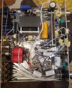
In a logical world one would move the HPA not the transformer ") An aluminium chassis is a good choice.
An aluminium chassis is a good choice.
Yes when I write C2 and C3 I mean C2 and C3 as that makes life way simpler. Just like I wrote CRC/CLC if you want the very best. Possibly the volume control is best supplied with separate regulators. The chosen opamp is unknown to me as I have never used that one but it is a fast one so again a recommendation to use an input RC low pass filter to have it amplifying audio signals only.
My compliments on the direct improvement in posting. You should however read posts/reactions a bit more careful as you seem to have missed some directions regarding AC coupling the HPA. It would not surprise me that the hum becomes less as well. And eh... please have the thread split up.
An aluminium chassis is a good choice.Yes when I write C2 and C3 I mean C2 and C3 as that makes life way simpler. Just like I wrote CRC/CLC if you want the very best. Possibly the volume control is best supplied with separate regulators. The chosen opamp is unknown to me as I have never used that one but it is a fast one so again a recommendation to use an input RC low pass filter to have it amplifying audio signals only.
My compliments on the direct improvement in posting. You should however read posts/reactions a bit more careful as you seem to have missed some directions regarding AC coupling the HPA. It would not surprise me that the hum becomes less as well. And eh... please have the thread split up.
Last edited:
Fast opamps love to oscillate on prototype boards. You’ll need an oscilloscope to see what’s going on. Even with a good layout I had opamps oscillating at 28Mhz. Some LM6171s were oscillating near 100Mhz!
Also you don’t need an input or output cap if your source has no DC offset.
Also you don’t need an input or output cap if your source has no DC offset.
Good design practice is to make stuff according standards. No one knows what source will be connected (audio friend comes by with the latest Yang Hu 32 bit DAC from Aliexpress...) and also is nothing ideal so DC offset is very well possible. Always the minimum and also maximum of 1 coupling cap in DC coupled systems to avoid disaster. DC offset at the input being amplified has most impact so I would use an input cap and an input filter.
It is indeed not wise to use such fast opamps on breadboard but OP has already the technique of "just doing something" and ask later why it has issues also being somewhat selective in replying to suggestions. I think I already tried to make that clear.
It is indeed not wise to use such fast opamps on breadboard but OP has already the technique of "just doing something" and ask later why it has issues also being somewhat selective in replying to suggestions. I think I already tried to make that clear.
Last edited:
Fast opamps love to oscillate on prototype boards. You’ll need an oscilloscope to see what’s going on. Even with a good layout I had opamps oscillating at 28Mhz. Some LM6171s were oscillating near 100Mhz!
Also you don’t need an input or output cap if your source has no DC offset.
LM6171?.. Like a HPA and on wires?.. It's named: HARDCORE.
AD817ANZ from aliexpress or genuine?Hey guys,
I will post a picture of the chassis with all the parts so you guys can visualize what's going on. I took a look at the marking on the chips for the headphone amp AD817AN.
Nigel yes the 0v is grounded.
[
Hey guys,
So the muting relay works great and the amp sounds good.
There's no hum or noise now.
So now to sort out the headphone amp. Perhaps someone has some suggestions. Right now there's a pretty loud hum in the headphones and the amp sounds distorted. Here's the schematic. The hum may be due to layout. The circuit board and input wires for the headphone amp are close to the transformer. I'm going to change the input wire to shielded cable. Hopefully that works.
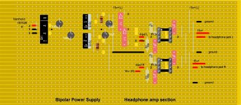
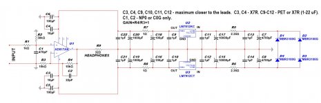
Maybe like that...
Attachments
Fast opamps love to oscillate on prototype boards. You’ll need an oscilloscope to see what’s going on. Even with a good layout I had opamps oscillating at 28Mhz. Some LM6171s were oscillating near 100Mhz!
Also you don’t need an input or output cap if your source has no DC offset.
I wonder if that's the problem? I do have an oscilloscope. I'm still learning how to use it, i used it a few months ago for the first time.
Hey Daymon1983
I believe they are original AD817ANZ. My friend gave them to me, i think he has other chips we could try.
Thanks for the attached schematic. I'll have a look at it.
AD817ANZ not bad OPamp, but for headphones need more output power, there is better something of AD825, AD8065 (8066 - dual version of 65), or THS4061 (4062). It's if you need only OPamp. Much better used OPamp+simple diamond buffer without NFB like Lehmann BCL schematic.
Just like that, or something
Attachments
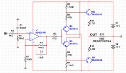
I find the feedback resistor and decoupling capacitor values in Damon's schematic to be unreasonably high, but maybe I am missing something.
@Gregas: Maybe Linear Technology AN-47 by Jim Williams would be worth a read for you?
No one bothers to reduce them.
- Home
- Amplifiers
- Headphone Systems
- help with op amp headphone amp hum and distortion