A combination of low offset /low input current OPA828 should keep DC offset on output < 1 mV without the need for a servo .
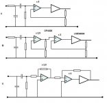
For a HP amp with a gain of around 5 , what would be the best :
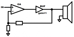
A ) One non-inv OPA828 with gain of 5 and with LME49600 in feedback .
B ) Two non-inv OPA828's with lower gain each , last one with LME49600 in feedback.
C ) Two inverting OPA828's with lower gain each , last one with LME49600 in feedback. ( inverting reduces overshoot according to datasheet , but THD is the same).
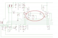
Any pitfalls like freq compensation or whatever that is in the pic below with the simular OPA827 in agdr O2 booster?
For a HP amp with a gain of around 5 , what would be the best :
A ) One non-inv OPA828 with gain of 5 and with LME49600 in feedback .
B ) Two non-inv OPA828's with lower gain each , last one with LME49600 in feedback.
C ) Two inverting OPA828's with lower gain each , last one with LME49600 in feedback. ( inverting reduces overshoot according to datasheet , but THD is the same).
Any pitfalls like freq compensation or whatever that is in the pic below with the simular OPA827 in agdr O2 booster?
Attachments
Ok , I guess no-one build one With OPA828 + LME49600.
In my quest to find answers to my questions on LME49600 in a loop with a quality opamp, and get some design tips , I read the entire "The Wire" thread ... it took me a long time. "The Wire" Ultra-High Performance Headphone Amplifier - PCB's
Here are some thoughts :
What struck me is OPC stated that this is not a HPamp for people that don't know
what kind of source they connect to it , regarding DC on the input of "the Wire" caused by the source.
That counted me out . Although I don't like a cap on the input , it is a necessity with some sources and protects the source's output .
Some ask for DC protection , but to keep it "a wire" , no DC protection. I don't see why a relay with the 2 contacts parallel would be a problem. I certainly want to protect my HP's.
Apparently no on/off noises with the "wire" , (hard to believe) , another thing that relays would mute.
I was anticipating some posts of angry DIY'ers that had their expensive HP blown up , but not one !! Remarkable because many were hesitant (and some their first time) using SMD's.
That was 2010-2011 ! I've been soldering SMD's since 1990 with a 2 $ soldering iron , without major problems.
OPC/Owen shows some pretty impressive graphs of noise/ distortion , and this with only a simple and standard use LM317-337 combo .
A thought for all the folks that want the expensive low noise LDO's .So all the work Elvee put in the "DeNoiser" , and that I build , seems pretty useless for HPamps.
Of course the Jfet family OPA627 - 827 -828 has rather midiocre neg PSRR , the now obselete LME49990 , probably better . ( LME49600 not that great , 75 dB , 65 at 20khz , no neg PSRR given in datasheet. BUF634A btw not much better.)
LME49990 must have been so stable that no freq compensation was needed , unlike OPA1611 - LME49600 or OPA827 - LME49600.
LME49600 in Dpak apparently had enough with the copper on both sides of the PCB to cool. Only used in balanced out , OPC used a heat sink..
Still some insist a BUF634A in SOIC can take the same heat ?
One question was asked about the 3rd layer groundplane , a question I too had , and is of special interest for DIY'ers , but OPC did not answer that.
Is a 3rd or even 4th layer needed for an HPamp ? What are on these layers , except for a shielding groundplane? For people like me who really do DIY from scratch , not sending gerber files to some chinese PCB maker , can I stick 2 epoxy PCB's together to have that 3rd layer ? Isn't this double thick PCB better because top and bottom (and the 3rd layer) tracks are further from each other so , less capacitance ?
While most designs have a HF filter in the input , OPC didn't want it ...Phase shift or something .
Really , is a 200pF to the ground after 1k , going to cause anything in the audio range and above ?
And then NvAvGuy/rocketscientist tread about building the National LME49600 HP application with LME49720 and servo . https://www.diyaudio.com/forums/hea...600-reference-design-project.html#post2523423
It looked appealing to me although I'd rather not have a servo.
It is said by some that despite the servo they still had dc offset on the output.
To me that sounds like they had some HF oscillation , that measured like an offset.
Is a fast opamp for servo needed ?
I've seen lots of slow OPA177's as servo's like in my power amp (and the paralleled NE5532 power amp from Douglas Self).
The 1k resistor after the servo bothered me too.
In all designs I've seen with servo's , that should be a 1 to 10 Mohm resistor , 1k ?? I don't get it.
NvAvGuy/rocketscientist quit that project , to go on to come up with the now "world famous" O2 HPamp.
It is not really for me but it is good to learn from , and many people are happy with it. It's simple , runs on batteries and is cheap.
And finally Agdr 's O2 booster.
O2 headamp output booster PCB
The project is the closest to what I would like to build : OPA827 + LME49600.
Here too , I've read the whole thread.
But the frequency compensation between OPA827 and LME49600 , was a suggestion by another DIY'er , which agdr took over into his design , without a real conversation/explanation about it.
It was changed from connecting a resistor to the ground to the feedback , but again barely a mention. What are the consequences using this ? Can it degrade the audio?
Here no graphs like "the Wire" . Then the 750 R resistor to the LME , is not explained. The slewrate of the LME is a lot bigger than the already fast OPA827 , so limiting the current to the LME 's input diodes doesn't seem necessary , the LME can keep up with anything the OPA is feeding it. 750 R is just another noise adder.
Because the OPA828 is an upgrade of the OPA827 , both opamps are very simular, this freq comp would be necessary too for my design.
Then to comeback to Elvee's DeNoiser . Throughout that thread , we know that output impedance of the supply is important , BUT agdr puts a 1R + 2,2uF on the supply of the OPA which clearly degrades the impedance to that opamp.
And he puts 2,2uF X7R near the LME , the Denoiser goes unstable with low ESR caps , so that's a no go for me.
And .... Too much gain ?
I did not explain it right.
Often I have movies on my computer were the sound is rather quiet . (youtube sometimes too ) .
Even with 32 ohm HP max vol , it is not enough . Max volume with 300 ohm HP is far to low, with quiet movies , even lower.
Yes for after a cd player no gain, is enough , even with 300 ohms , but computer and mp3 player on 1 Li batt , needs more gain.
Maybe the 5-6 is too much , maybe 4 would be enough , but it would still be a question of 1 opamp with gain of 4 , or 2 opamps with 2 x 2 or even 4 x and 1x to drive the LME buffer.
Inverting = less overshoot with capacitance on output and a freq comp filter are (small) caps . Commonmode is also beter , the 2 inputs stay 0 V.
But again with signals on the input usually 1 -2 V peak so very close to the ground , does that matter much ?
In my quest to find answers to my questions on LME49600 in a loop with a quality opamp, and get some design tips , I read the entire "The Wire" thread ... it took me a long time.
"The Wire" Ultra-High Performance Headphone Amplifier - PCB'sHere are some thoughts :
What struck me is OPC stated that this is not a HPamp for people that don't know
what kind of source they connect to it , regarding DC on the input of "the Wire" caused by the source.
That counted me out . Although I don't like a cap on the input , it is a necessity with some sources and protects the source's output .
Some ask for DC protection , but to keep it "a wire" , no DC protection. I don't see why a relay with the 2 contacts parallel would be a problem. I certainly want to protect my HP's.
Apparently no on/off noises with the "wire" , (hard to believe) , another thing that relays would mute.
I was anticipating some posts of angry DIY'ers that had their expensive HP blown up , but not one !! Remarkable because many were hesitant (and some their first time) using SMD's.
That was 2010-2011 ! I've been soldering SMD's since 1990 with a 2 $ soldering iron , without major problems.
OPC/Owen shows some pretty impressive graphs of noise/ distortion , and this with only a simple and standard use LM317-337 combo .
A thought for all the folks that want the expensive low noise LDO's .So all the work Elvee put in the "DeNoiser" , and that I build , seems pretty useless for HPamps.
Of course the Jfet family OPA627 - 827 -828 has rather midiocre neg PSRR , the now obselete LME49990 , probably better . ( LME49600 not that great , 75 dB , 65 at 20khz , no neg PSRR given in datasheet. BUF634A btw not much better.)
LME49990 must have been so stable that no freq compensation was needed , unlike OPA1611 - LME49600 or OPA827 - LME49600.
LME49600 in Dpak apparently had enough with the copper on both sides of the PCB to cool. Only used in balanced out , OPC used a heat sink..
Still some insist a BUF634A in SOIC can take the same heat ?
One question was asked about the 3rd layer groundplane , a question I too had , and is of special interest for DIY'ers , but OPC did not answer that.
Is a 3rd or even 4th layer needed for an HPamp ? What are on these layers , except for a shielding groundplane? For people like me who really do DIY from scratch , not sending gerber files to some chinese PCB maker , can I stick 2 epoxy PCB's together to have that 3rd layer ? Isn't this double thick PCB better because top and bottom (and the 3rd layer) tracks are further from each other so , less capacitance ?
While most designs have a HF filter in the input , OPC didn't want it ...Phase shift or something .
Really , is a 200pF to the ground after 1k , going to cause anything in the audio range and above ?
And then NvAvGuy/rocketscientist tread about building the National LME49600 HP application with LME49720 and servo . https://www.diyaudio.com/forums/hea...600-reference-design-project.html#post2523423
It looked appealing to me although I'd rather not have a servo.
It is said by some that despite the servo they still had dc offset on the output.
To me that sounds like they had some HF oscillation , that measured like an offset.
Is a fast opamp for servo needed ?
I've seen lots of slow OPA177's as servo's like in my power amp (and the paralleled NE5532 power amp from Douglas Self).
The 1k resistor after the servo bothered me too.
In all designs I've seen with servo's , that should be a 1 to 10 Mohm resistor , 1k ?? I don't get it.
NvAvGuy/rocketscientist quit that project , to go on to come up with the now "world famous" O2 HPamp.
It is not really for me but it is good to learn from , and many people are happy with it. It's simple , runs on batteries and is cheap.
And finally Agdr 's O2 booster.
O2 headamp output booster PCB
The project is the closest to what I would like to build : OPA827 + LME49600.
Here too , I've read the whole thread.
But the frequency compensation between OPA827 and LME49600 , was a suggestion by another DIY'er , which agdr took over into his design , without a real conversation/explanation about it.
It was changed from connecting a resistor to the ground to the feedback , but again barely a mention. What are the consequences using this ? Can it degrade the audio?
Here no graphs like "the Wire" . Then the 750 R resistor to the LME , is not explained. The slewrate of the LME is a lot bigger than the already fast OPA827 , so limiting the current to the LME 's input diodes doesn't seem necessary , the LME can keep up with anything the OPA is feeding it. 750 R is just another noise adder.
Because the OPA828 is an upgrade of the OPA827 , both opamps are very simular, this freq comp would be necessary too for my design.
Then to comeback to Elvee's DeNoiser . Throughout that thread , we know that output impedance of the supply is important , BUT agdr puts a 1R + 2,2uF on the supply of the OPA which clearly degrades the impedance to that opamp.
And he puts 2,2uF X7R near the LME , the Denoiser goes unstable with low ESR caps , so that's a no go for me.
And .... Too much gain ?
I did not explain it right.
Often I have movies on my computer were the sound is rather quiet . (youtube sometimes too ) .
Even with 32 ohm HP max vol , it is not enough . Max volume with 300 ohm HP is far to low, with quiet movies , even lower.
Yes for after a cd player no gain, is enough , even with 300 ohms , but computer and mp3 player on 1 Li batt , needs more gain.
Maybe the 5-6 is too much , maybe 4 would be enough , but it would still be a question of 1 opamp with gain of 4 , or 2 opamps with 2 x 2 or even 4 x and 1x to drive the LME buffer.
Inverting = less overshoot with capacitance on output and a freq comp filter are (small) caps . Commonmode is also beter , the 2 inputs stay 0 V.
But again with signals on the input usually 1 -2 V peak so very close to the ground , does that matter much ?
Last edited:
It is meant for mp3 player & computer with a 1,5V to 2Vpp output and mostly with 300 ohm HP's
2Vpp is very low for a soundcard output. Get a good soundcard, nowadays it's 2Vrms output.
It's a older laptop with audio chip on the motherboard . Switching soundcards is impossible .
2Vrms with 300 ohm HP's and a movie with low volume is not enough.
Let's not keep hammering on the gain. Whether is is 2 x or 5 x , it doesn't matter much.
"The wire" had the option to change the gain by changing resistors.
2Vrms with 300 ohm HP's and a movie with low volume is not enough.
Let's not keep hammering on the gain. Whether is is 2 x or 5 x , it doesn't matter much.
"The wire" had the option to change the gain by changing resistors.
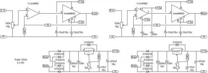
Did the same with lm4562. No input cap no dc servo. 4.7 gain. Best HP amp i have, sounds better then my 300b se tube HP amp. I use AKG 7XX special edition.
Just for fun
Just change power supply to +/- 15v for 300ohm headphone.
Just for fun
Just change power supply to +/- 15v for 300ohm headphone.
Attachments
Last edited:
Thanks for your reply Koifarm , not many seem interested in this .
Looking at your circuit : not a 4,7 gain . Even if you switch the 1k and 4k7 it will be a 5,7 gain. What kind of offset you have with the LM4562 ?
With the volume at half ( 50k ) , that is going to be 500 uV x your gain (4,7 ?) = at least 2,35 mV depending on the input offset of the LM.
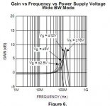
What I am concerned about is oscillation. The wire with LME49990 and your LM4562 have no freq compensation. I assumed that the oscillation risk was the opamp , like Neurochrome in his HP1 said , the OPA1611 was the problem. I went back to the O2 booster , and in post 23, Shaq888 writes and shows : "LME49600 has an ugly peak around 100MHz. It look bad in combination almost with any opamp if you do not put any additional freq compensation around."
So the LME49600 seems to be the problem ?
Just copying the compensation there , OPA828 is very much like the OPA 827 , there is still what he writes in post 35 : "with unity gain you can connect 3.3k resistor to output of LME with very similar result."
So things differ when there is gain ?
I was hoping to get some feedback on the third (middle) layer when designing a HPamp PCB , but I must have bad B.O , because not much response here.
Looking at your circuit : not a 4,7 gain . Even if you switch the 1k and 4k7 it will be a 5,7 gain. What kind of offset you have with the LM4562 ?
With the volume at half ( 50k ) , that is going to be 500 uV x your gain (4,7 ?) = at least 2,35 mV depending on the input offset of the LM.
What I am concerned about is oscillation. The wire with LME49990 and your LM4562 have no freq compensation. I assumed that the oscillation risk was the opamp , like Neurochrome in his HP1 said , the OPA1611 was the problem. I went back to the O2 booster , and in post 23, Shaq888 writes and shows : "LME49600 has an ugly peak around 100MHz. It look bad in combination almost with any opamp if you do not put any additional freq compensation around."
So the LME49600 seems to be the problem ?
Just copying the compensation there , OPA828 is very much like the OPA 827 , there is still what he writes in post 35 : "with unity gain you can connect 3.3k resistor to output of LME with very similar result."
So things differ when there is gain ?
I was hoping to get some feedback on the third (middle) layer when designing a HPamp PCB , but I must have bad B.O , because not much response here.
Rick, do you have the .pdf of "Operational Amplifiers - Theory and Practice" from James K. Roberge? If not, it is available on MIT Open Courseware. It has a good chapter on the basics of OpAmp compensation and also discusses two pole compensation. Then there are countless discussions on compensation topics here on DIYaudio. Many of them originated in Bob Cordell's threads. There are some threads with links to where the more interesting discussions started, maybe look in the solid state forum. I remember seeing one quite recently.
LME49600 has a nasty gain peak at 100-ish MHz. Also, the SPICE model does not include capacitive loading at all if I remember correctly (in contrast to BUF634 - you can search the TI forums or fire up SPICE to confirm this). Just some things to keep in the back of your head when using this IC.
LME49600 has a nasty gain peak at 100-ish MHz. Also, the SPICE model does not include capacitive loading at all if I remember correctly (in contrast to BUF634 - you can search the TI forums or fire up SPICE to confirm this). Just some things to keep in the back of your head when using this IC.
I measure very low offset, between 2 and 5mV.
About oscilation, i can only measure untill 1Mhz.
There is no oscilation and no hot lm4562 and/or LME49600.
In the thread " just for fun" i use single sided PCB. This works great for me.
There could be HF oscillation but you don't notice or can measure it.
I wonder if there is lets say 100 Mhz oscillation , would that be big voltages , like 1 to 5 V swings or just 10-100mV on top of the signal , and would you even notice that listening through HP's ?
Yes I've seen your PCB , but then again here on DIYaudio , many go with 3 or even 4 layers for a simple HP amp. Mine needs to be compact even with a big MKP and relay on it.
I only use through the hole components when there is no SMD available or when dissipation is too high for SMD or testing . SMD's are only use once.
Kn0ppers :
Thanks for the link , I'll have a look at that .
I don't have a background in electronics and I don't use simulations like SPICE . It's just too hard for me. That's why I'm looking here on the forum .
It's just weird that some people have no problem using buffers like the LME and the BUF's without any compensation , even on simple one sided PCB's , and others do use it .
I think because of the smd and multilayer they have oscilations.
I have build a lot of phono preamps, the ones with simple groundplanes and just one layer had much less probems with humm and hiss. I also build a lot of HF transmitters. Same there just hardwire or simple PCB have less problems. To design a good multilayer is more difficult then a good single layer.
A good metal case and decoupling in and outputs keeps the trouble outside the box.
Last edited:
Bad designed multilayer PCB could be a factor but I doubt SMD's with their shorter pens pose a bigger risk. If you open VHF TV receivers , it's all small SMD's. A metal case isn't going to stop oscillation because of a nasty gain peak of an IC.
The "Theory and Practice" from James K. Roberge" , about compensation is way over my head.
Trail and error approach is kind of pricey with the OPA828 and LME49600.
Here's the LME49600 peak in another pic. According to the datasheet , the BUF634A doesn't seem to have this 100 Mhz peak .
The "Theory and Practice" from James K. Roberge" , about compensation is way over my head.
Trail and error approach is kind of pricey with the OPA828 and LME49600.
Here's the LME49600 peak in another pic. According to the datasheet , the BUF634A doesn't seem to have this 100 Mhz peak .
Attachments
OK , nearly a year later !
I don't want to start anoher thread and it is very much related to this one , so here are some questions about designing a PCB for a HPamp that I'm struggling with :
Designing PCB's for low freq or static digital logic is easy and fun , but analog with
high performance / high speed opamps like OPA828 and the LME49600 buffer , is
different , especially if you want it compact and not oscillating...
The signal tracks to and from opamps (in smd) are on one side of the PCB and
easy (although not 100 % like the datasheets suggested layout) , but the power lines on the other side are not.
I tried online PCB design like easyeda.com to see how that would do it , but I can't make it work (says it is not a circuit ,) , and will it really do it the way it should be done ?
What's the consensus on supply tracks and groundplanes under opamps these days?
Like I said : The signal tracks to and from opamps (in smd) are on one side of the
PCB . Is it ok to have : * supply tracks
* ground lines for decouple caps
* groundplanes that conduct return currents
* and groundplanes that only shield on the other side of the PCB under the opamps .
under the opamp inputs or the feedback (gain) resistors ?
I know crossing signal tracks with supply tracks is better than paralleling them .
When an input is connected to the low impedance of an opamp output , does it
matter that there is potential supply line noise on the other side of the PCB ?
What if I elevated the power tracks ( and even ground current tracks) so that it is more than the thickness of the 1,5 mm epoxy PCB , like with a wire bridge or in places where they come close , use a piece of PCB on top ( even with a 3rd layer in between connected to the ground to shield ) , so that they are 3 mm apart ?
And : Can the coil magnetism of a relay near an amp IC , influence the signal ?
I don't want to start anoher thread and it is very much related to this one , so here are some questions about designing a PCB for a HPamp that I'm struggling with :
Designing PCB's for low freq or static digital logic is easy and fun , but analog with
high performance / high speed opamps like OPA828 and the LME49600 buffer , is
different , especially if you want it compact and not oscillating...
The signal tracks to and from opamps (in smd) are on one side of the PCB and
easy (although not 100 % like the datasheets suggested layout) , but the power lines on the other side are not.
I tried online PCB design like easyeda.com to see how that would do it , but I can't make it work (says it is not a circuit ,
) , and will it really do it the way it should be done ?What's the consensus on supply tracks and groundplanes under opamps these days?
Like I said : The signal tracks to and from opamps (in smd) are on one side of the
PCB . Is it ok to have : * supply tracks
* ground lines for decouple caps
* groundplanes that conduct return currents
* and groundplanes that only shield on the other side of the PCB under the opamps .
under the opamp inputs or the feedback (gain) resistors ?
I know crossing signal tracks with supply tracks is better than paralleling them .
When an input is connected to the low impedance of an opamp output , does it
matter that there is potential supply line noise on the other side of the PCB ?
What if I elevated the power tracks ( and even ground current tracks) so that it is more than the thickness of the 1,5 mm epoxy PCB , like with a wire bridge or in places where they come close , use a piece of PCB on top ( even with a 3rd layer in between connected to the ground to shield ) , so that they are 3 mm apart ?
And : Can the coil magnetism of a relay near an amp IC , influence the signal ?
It would help to post more substantive suggestion than audiophile myth.It probably won't sound as good as a design more focused on audio SQ.
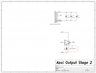
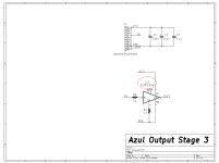
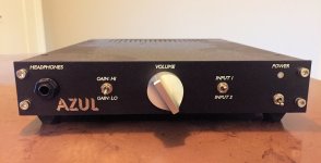
I brought an HPA called "Azul" to the 2019 Burning Amp Festival, and let people listen to it, either through the headphones I brought or through their own. Folks were generally positive about the sonics.
It was a composite amplifier using an LM4562 (bandwidth = 55 MHz) and an LH0033 video buffer (BW 100 MHz). Worked great, no stability issues, thru-hole components soldered to 2-layer PCB.
What might be interesting about Azul, is this: I was paranoid about destroying my obsolete, rare, and expensive LH0033s during initial bring-up and testing. So I built some pin-compatible daughter cards that plugged into the LH0033 socket and "emulated" the LH0033 (video speed 1X buffer). One of them used the LME49600, as mentioned in the title of this Forum thread. (see attachments). Small world.
_
Attachments
Wow , thanks for your post , it is so not helpful.Why try to make an HPA that is fast enough to be a video amp? It probably won't sound as good as a design more focused on audio SQ.
Your answer to any of my questions is : use slower opamps .
Now why didn't I think of that.
NwAvGuy somewhere in his O2 blog writes that for audio , you don't need more
than 2-3 V/us and used NJM4556 with 3V/us , yet he started to make the
LME49600 HPamp like the application note , see above, but couldn't cut it so he made the O2.
I disagree with his slew rate statement , but I'm just a hobbyist/amateur.
Tell it to all the folks here that have fast opamps with the super fast LME 49600 or BUF634A (and other fast) buffers.
I didn't choose OPA828 for its speed , that was just a bonus , but I need layout
information to tame that beast. This is what the DIYaudio forum is about , isn't it ?
- Home
- Amplifiers
- Headphone Systems
- Anyone make OPA828 - LME49600 combination