Ok, that was nasty. There wasn't a single component but the interaction between a number of components. I simplified the output to a single tube on one side.
Output at the load:

Starting from the front of the amp:
1. The driver tube outputs I used a 730 and then a 31K load, this was interacting with the couping caps behind it (0.22+1u)
2. The coupling caps were interacting with the bias and grid leak for the circlotron and the voltage divider I was using to reduce input level into the ecc99s.
3. The output tube, although I thought was isolated all the way to ground with even a B+ isolation was still coupled and seeing the opposite phase's non-isolated phase shift.
4. And all that was lovely playing with the ecc99 grid capacitance.
So the outcome to fix this:
a) switch to the driver cathode biasing the tube cascode.
b) remove the coupling caps entirely from the driver-cascode
c) remove the cascode input level dividers and grid leak.
I've used the same before without issue so I suspect that for circlotrons the same approaches have side effects.
I suspect that Atmasphere had similar phase shift issues hence biasing via the drivers
Anyway.. today is going to be a busy day.. so probably a slow down of updates")
Output at the load:
Starting from the front of the amp:
1. The driver tube outputs I used a 730 and then a 31K load, this was interacting with the couping caps behind it (0.22+1u)
2. The coupling caps were interacting with the bias and grid leak for the circlotron and the voltage divider I was using to reduce input level into the ecc99s.
3. The output tube, although I thought was isolated all the way to ground with even a B+ isolation was still coupled and seeing the opposite phase's non-isolated phase shift.
4. And all that was lovely playing with the ecc99 grid capacitance.
So the outcome to fix this:
a) switch to the driver cathode biasing the tube cascode.
b) remove the coupling caps entirely from the driver-cascode
c) remove the cascode input level dividers and grid leak.
I've used the same before without issue so I suspect that for circlotrons the same approaches have side effects.
I suspect that Atmasphere had similar phase shift issues hence biasing via the drivers
Anyway.. today is going to be a busy day.. so probably a slow down of updates
Last edited:
The current schematic:

I noted that the driver input voltage divider is adding a very very small bass phase increase, so I will also have a look at that later - hence the big capitals.
I'm happy that the back end is feeling better, the cascode is, in reality, probably creating too much gain ... but I have a couple of ideas on that which do not use voltage dividers near caps but possibly use some local negative feedback to reduce signal level.

I wrote a lovely post only to be told my token had expired..
That will do - given an LTSpice sim is about as precise and accurate as a game of pin the donkey at a state level. It does give a general picture of things working or not which can curtail the obvious and the oblivious.

It's currently configured for my 104dBV headphones and CD player which I've measured 1.5V peak on some CDs. Let's be clear - I've seen this push 24V and 450mA just as happily as the values below (I have a 24V TVS across the load - an idea stolen from UltimateX86's schematic).
Input -> Output
-10dB 447mV -> 290mV, 5.2mA
-3dB 1V -> 650mV, 11.1mA
1.5V -> 960mV, 17.5mA
+10dbV 3.16Vrms 4.5Vpeak -> 2.14V +3.6dB
Mark - thank you for the link and the graphs.
I feel like I've learnt a lot about tube amps, some solid state, and cascodes attempting this project.
At 6am I found these two interesting articles which got me thinking more and why people seem to have issue with cascodes - more importantly their misunderstanding of them. So perhaps these musings and learnings will help people interested:
* Nelson Pass's article: https://www.firstwatt.com/pdf/art_cas_amp.pdf
* Broskie's interesting adaptations: Retrograde Cascode
A Cascode:
* consists of a V-to-I converter then a V-to-I converter.
* use of constant votlage/ground on V-to-I means virtually no miller effect as there's a constant charge on the grid. So no capacitance issues means higher frequency response.
* linearises the tube's characteristics
* linear lines = less asymmetric distortion on the load line = less even harmonics.
* linear lines = more symmetrical distortion = more odd harmonics (but not much see next points)
* triode normal cascode has low power output so should be driving a high impedance load.
* cascode (unfolded) needs voltage headroom to convert I-to-V without clipping and adding odd harmonics or intermodulation.
* is a gain machine, with 17mu 12BH7As it's entirely possible to get 100Vpp output from under 2V for example. See my point about headroom.
The interesting piece from Broskie is essentially using the V-to-I from the bottom.. a cathode follower as a suggestion. Interesting but given I've not seen many like that.. I'm less inclined to waste time on that. However Nelson highlights the use of Dayton-Wright as a further improvement over the standard cascode that drops harmonics further. Interesting.. perhaps a change to play with in future.
So my musings this morning also covered the general structure of the amp. The use of a cascode, drivers and the output section plus the specifics of the tubes in use - the 12BH7A and the ecc99. The achilles heal of the ecc99 is the input voltage range, and to a lesser extent the the same issue occurs with the 12BH7A.
The 12BH7A can take 20Vpp but will be letting you know. The ecc99 will give you the middle finger so sticking with 10Vpp is probably recommended.
The cascode of the design can be made to provide anything from 2V to 100Vpp, with a driver requirement a good 2-5Vpeak input is useful to sit at -10V bias and have current available to drive with the BH7. However chaining a ecc99 with it's 10Vpp input is a bit like drinking a straw whilst pinching the straw. It doesn't make sense (being objective).
This is where the M60 would be driving the low-mu 6AS7 which would be very happy with 20-40Vpp or more input. So you can see the voltage gain through the amp. You could do exactly the same 6AS7 for headphones too as tube only but you would have higher Zout than this hybrid.
I've also learn a lot about cascode interactions with negative feedback and phase shift.. I can see why the M60 uses the driver output to bias the output stage due to the additional phase shift adding coupling caps would add.
I also see why the M60 uses 0.1uF coupling caps between the cascode and the driver (not just to decouple) but the value also introduces a rolloff under 10Hz so by the time it's below 1Hz it's well attenuated to prevent LF instability. Additionally the 4.73Kohm resistor on the input prevents HF noise from causing instability by rolling off - starting just before 10Khz. This makes the amp sound less forced at the top end but keeps a good airy nature.
The M60-inspired frontend is awesome and very flexible. Probably too awesome for a headphone amp (which is probably why they don't use it) and my backend is probably capable of simply taking a triode output and being just as good with all the H2 goodness you want.
However this is the achilles heel of running the same amp as a headphone and as a speaker amp:
* cascode + driver + tubes - be a swinger - free the voltage swing! The obvious point here is OTL or big output tubes with an OT.. those in a cyclotron could be run as SE..
* cascode + driver + hybrid backend with larger BJTs - this suffers from the ecc99's grid limitations that limit the voltage swing available without distortion.
* cascode + driver driving larger bjts - this would be an option, with a single driver being able to drive the larger base capacitance of the large BJTs. Simply parallel for additional wattage. This keeps with the philosophy of using the tube output to driver the speakers with the BJT assisting..
* cascade + driver + mosfet output stage - let it go.. simply drive the mosfet gate with the cascode or driver depending on the capacitance. High impedance input makes that possible.. this is just like UltimateX86's circlotron.
Given the size of the chassis, the power supply requirements and the additional supporting components real estate.. I'm tempted to keep it HP for now but test it out later with speakers..
That will do - given an LTSpice sim is about as precise and accurate as a game of pin the donkey at a state level. It does give a general picture of things working or not which can curtail the obvious and the oblivious.
It's currently configured for my 104dBV headphones and CD player which I've measured 1.5V peak on some CDs. Let's be clear - I've seen this push 24V and 450mA just as happily as the values below (I have a 24V TVS across the load - an idea stolen from UltimateX86's schematic).
Input -> Output
-10dB 447mV -> 290mV, 5.2mA
-3dB 1V -> 650mV, 11.1mA
1.5V -> 960mV, 17.5mA
+10dbV 3.16Vrms 4.5Vpeak -> 2.14V +3.6dB
Mark - thank you for the link and the graphs.
I feel like I've learnt a lot about tube amps, some solid state, and cascodes attempting this project.
At 6am I found these two interesting articles which got me thinking more and why people seem to have issue with cascodes - more importantly their misunderstanding of them. So perhaps these musings and learnings will help people interested:
* Nelson Pass's article: https://www.firstwatt.com/pdf/art_cas_amp.pdf
* Broskie's interesting adaptations: Retrograde Cascode
A Cascode:
* consists of a V-to-I converter then a V-to-I converter.
* use of constant votlage/ground on V-to-I means virtually no miller effect as there's a constant charge on the grid. So no capacitance issues means higher frequency response.
* linearises the tube's characteristics
* linear lines = less asymmetric distortion on the load line = less even harmonics.
* linear lines = more symmetrical distortion = more odd harmonics (but not much see next points)
* triode normal cascode has low power output so should be driving a high impedance load.
* cascode (unfolded) needs voltage headroom to convert I-to-V without clipping and adding odd harmonics or intermodulation.
* is a gain machine, with 17mu 12BH7As it's entirely possible to get 100Vpp output from under 2V for example. See my point about headroom.
The interesting piece from Broskie is essentially using the V-to-I from the bottom.. a cathode follower as a suggestion. Interesting but given I've not seen many like that.. I'm less inclined to waste time on that. However Nelson highlights the use of Dayton-Wright as a further improvement over the standard cascode that drops harmonics further. Interesting.. perhaps a change to play with in future.
So my musings this morning also covered the general structure of the amp. The use of a cascode, drivers and the output section plus the specifics of the tubes in use - the 12BH7A and the ecc99. The achilles heal of the ecc99 is the input voltage range, and to a lesser extent the the same issue occurs with the 12BH7A.
The 12BH7A can take 20Vpp but will be letting you know. The ecc99 will give you the middle finger so sticking with 10Vpp is probably recommended.
The cascode of the design can be made to provide anything from 2V to 100Vpp, with a driver requirement a good 2-5Vpeak input is useful to sit at -10V bias and have current available to drive with the BH7. However chaining a ecc99 with it's 10Vpp input is a bit like drinking a straw whilst pinching the straw. It doesn't make sense (being objective).
This is where the M60 would be driving the low-mu 6AS7 which would be very happy with 20-40Vpp or more input. So you can see the voltage gain through the amp. You could do exactly the same 6AS7 for headphones too as tube only but you would have higher Zout than this hybrid.
I've also learn a lot about cascode interactions with negative feedback and phase shift.. I can see why the M60 uses the driver output to bias the output stage due to the additional phase shift adding coupling caps would add.
I also see why the M60 uses 0.1uF coupling caps between the cascode and the driver (not just to decouple) but the value also introduces a rolloff under 10Hz so by the time it's below 1Hz it's well attenuated to prevent LF instability. Additionally the 4.73Kohm resistor on the input prevents HF noise from causing instability by rolling off - starting just before 10Khz. This makes the amp sound less forced at the top end but keeps a good airy nature.
The M60-inspired frontend is awesome and very flexible. Probably too awesome for a headphone amp (which is probably why they don't use it) and my backend is probably capable of simply taking a triode output and being just as good with all the H2 goodness you want.
However this is the achilles heel of running the same amp as a headphone and as a speaker amp:
* cascode + driver + tubes - be a swinger - free the voltage swing! The obvious point here is OTL or big output tubes with an OT.. those in a cyclotron could be run as SE..
* cascode + driver + hybrid backend with larger BJTs - this suffers from the ecc99's grid limitations that limit the voltage swing available without distortion.
* cascode + driver driving larger bjts - this would be an option, with a single driver being able to drive the larger base capacitance of the large BJTs. Simply parallel for additional wattage. This keeps with the philosophy of using the tube output to driver the speakers with the BJT assisting..
* cascade + driver + mosfet output stage - let it go.. simply drive the mosfet gate with the cascode or driver depending on the capacitance. High impedance input makes that possible.. this is just like UltimateX86's circlotron.
Given the size of the chassis, the power supply requirements and the additional supporting components real estate.. I'm tempted to keep it HP for now but test it out later with speakers..
So I’ve been thinking about slew rates and rise/fall times.
A 20V 20KHz signal needs a minimum of about 5V/uS according to some, however a sine wave at zero crossing is near vertical thus I would expect far higher. Thus any caps you use, to my thinking, would need to charge and discharge (5RC etc) within that time or transitional distortion and general symetrical distortions would rise (ie odd harmonics).
WIMA publish their V/uS for their caps. The metalised poly caps are around 5V/uS vs the likes of the MKP10 at a good 500V/uS to the FKP1 with a blinding 11000V/uS. I have no idea what the nichicon Muse ES are however given the ESR measured, it’s capacitance (330uF in this case) it’s making me wonder about the V/uS and 5RC time. Probably glacial compared to the FKP but from listening tests parallel muses seem a little murky compared to the FKP (no surprise).
I’m actually glad the pair of decoupling caps were removed - I now have a pair of MKP10 and FKP1s from each channel free for recycling into the new backend..
However that learning is for another day.
Why not use good old mathematics? The "slew rate" of a given voltage waveform is its maximum dV/dt. Calculating that for a sine wave y(t) = A * sin(2*pi*f*t), we find
dy/dt reaches its maximum when the cos() expression equals +1, thus
Working through some numerical examples:
Some designers employ a rule of thumb which includes their own personal integer "N":
Then they choose a value of N which gives them enough margin-of-safety to achieve peace of mind.
- dy/dt = 2*pi*f * A * cos(2*pi*f*t)
- max dy/dt = slew rate = 2*pi*f * A
for a sine wave with A = 5V and f = 20 kHz, slew rate = 6.28E+5 volts/second {0.628 volts per microsecond}
for a sine wave with A = 15V (max amplitude an opamp can produce when running from ±18V supply rails) and f = 140 kHz (7th harmonic of 20k), slew rate = 1.3E+7 volts/second {13 volts per microsecond}
for a sine wave with A = 15V (max amplitude an opamp can produce when running from ±18V supply rails) and f = 140 kHz (7th harmonic of 20k), slew rate = 1.3E+7 volts/second {13 volts per microsecond}
Some designers employ a rule of thumb which includes their own personal integer "N":
One of my design goals is to make my amplifier's slew rate be at least a factor of N times higher than the slew rate of a rail-to-rail 20 kHz sine wave.
Then they choose a value of N which gives them enough margin-of-safety to achieve peace of mind.
A 20V 20KHz signal needs a minimum of about 5V/uS according to some however a sine wave at zero crossing is near vertical thus I would expect far higher.
3.55 V/uS for 20 VRMS.
Thus any caps you use, to my thinking, would need to charge and discharge (5RC etc) within that time or transitional distortion and general symmetrical distortions would rise (ie odd harmonics).
Slewing is a nonlinearity designers need to watch out for, but it's not really a function of capacitor ESR.
WIMA publish their V/uS for their caps. The metalised poly caps are around 5V/uS vs the likes of the MKP10...
According to the MKP10 data sheet, the worst-case dV/dt spec is 30 V/uS for the 22-47 uF 100V range. That corresponds to a charging current of 660-1,410 Amperes. You're unlikely to have a problem with this in any practical audio circuit design.
I did look at the maths, although the 2pi*f rate gives a time (x axis) per second and the Vpeak gives the y axis, which in my mind is a triangle to the peak rather than the steepest differential of the sine curve. I’ll have to think on that more but I can see some validity for the N integer idea (like the rule of 10x sensing minimum for measurement at 1 unit precision).
I think a larger role is the speed of charge/discharge of devices connected. The second formulae was SR=Voltage gain*Isat/C from memory.
I think a larger role is the speed of charge/discharge of devices connected. The second formulae was SR=Voltage gain*Isat/C from memory.
I did look at the maths, although the 2pi*f rate gives a time (x axis) per second and the Vpeak gives the y axis, which in my mind is a triangle to the peak rather than the steepest differential of the sine curve. I’ll have to think on that more but I can see some validity for the N integer idea (like the rule of 10x sensing minimum for measurement at 1 unit precision).
I think a larger role is the speed of charge/discharge of devices connected. The second formulae was SR=Voltage gain*Isat/C from memory.
The formula for the instantaneous rate of change with respect to time of a voltage
v(t) = A * sin(wt)
is
v'(t) = A * w * cos(wt)
This is all you need to know. There is no guessing, no mystery.
The dV/dt figures on the capacitor data sheet are not relevant to the slew rate of the amplifier you might design using the capacitors.
Ok. That makes sense. Reading around the subject from this morning, I'm aware the slew rate in terms of an amp becomes the lowest component slew rate, be it due to opamp used, cap or particular filter with deliberate control over slew rate for stability. Coupling caps would be on the signal path hence are one part of the chain.
Ok. That makes sense. Reading around the subject from this morning, I'm aware the slew rate in terms of an amp becomes the lowest component slew rate, be it due to opamp used, cap or particular filter with deliberate control over slew rate for stability. Coupling caps would be on the signal path hence are one part of the chain.
You go to engineering school, they teach you (hopefully) how to think systematically about this stuff. You can jump to the wrong conclusions and just confuse yourself if you go at it willy-nilly. Just saying.
You go to engineering school, they teach you (hopefully) how to think systematically about this stuff. You can jump to the wrong conclusions and just confuse yourself if you go at it willy-nilly. Just saying.
Hehe, my day job is digital and IT, with some oddities like quantum cryptography hence a passing familiarity/critique with complex number wave functions and sine waves. So the world of amp design and tubes is a welcome change and a chance to have fun, learn and make mistakes (especially when not following process or procedure). I don't see much difference between systems/software design and amp design. There's quite a few step-by-step guides and books on that I've found in reading.
The requirement for low Zout was always part of the requirements, only shifting requirements at the end of design in an attempt to drive bigger speakers in addition to headphones is why there's some gnashing of teeth.

I've simplified the backend to remove unneeded components:
* the mirror BJT in the tube line isn't required - they are all connected so a cap bank provides all the required current that's required.
* removed cap banks - leaving one for the combined tubes and one for the BJTs base isolation. The multiple banks were, in fact, in parallel.
* stripped out resistors used for quazi-biasing - these, in a 60 second sim end up causing the system to fight. Biasing has to be via a negative to the grid (just like the original circlotron).
I've tuned up the tube side by disconnecting the BJTs (I may make this a switch) - this is the output at full 4V peak input and a full 160mA peak-to-peak across 55ohm:

That's enough not to worry about BJTs.. I'm just waiting for a sim to finish with the BJTs connected.. it balances nicely - the BJTs provide power and the tubes backoff their peak-to-peak voltage swings.

Bottom combined through load current (green)
Middle combined tube peak-to-peak (blue)
Top a single BJT current combined bias and signal (pink)
Last edited:
Just leaving this simulating for today - pure tube direct connected version (no isolating caps). This is essentially an M60 in class A only operation.

It's very well behaved on startup - load current with 1.5V peak input with the front end tuning the same as the capacitor version.

In terms of safety sims I need to try:
* Tube open
* Tube short
* PS short
* PS open
* startup with the above
* shutdown with the above
Logically, through inspection the amp rebalances but I want to check.
EDIT: updated 240Vrms.
It's very well behaved on startup - load current with 1.5V peak input with the front end tuning the same as the capacitor version.
In terms of safety sims I need to try:
* Tube open
* Tube short
* PS short
* PS open
* startup with the above
* shutdown with the above
Logically, through inspection the amp rebalances but I want to check.
EDIT: updated 240Vrms.
Last edited:
I've also been looking into the hybrid backend power supplies - in theory it would make sense to run the 40V and 150V from the same 40V power supply using a voltage multiplier for the lower current higher voltage. However both supplies are floating in their respective circlotrons and normally a voltage multiplier needs a zero reference (usually ground). I could make a virtual ground but this would mean that one circlotron is balanced but the other is likely to be out of balance. I could use two isolated secondaries off a customer toroid - one for 40V higher current, the other being 150V lower current. This would save space and probably be the easiest option. Getting both channels on a single transformer would be good.
As it is the power transformers will probably be:
* Toroid 1 - Cascode supply - two secondaries for rails +320 -320
* Toroid 2 - Left Circlotron B1 - two secondaries for rails +150, +150
* Toroid 3 - Right Circlotron B1 - two secondaries for rails +150 +150
* Toroid 4 - Right Circlotron B1 & B2 - four secondaries for rails +40 +40 +40 +40
* Toroid 5 - Heater supplies - two secondaries for heaters B+
* Small 5Vdc - housekeeping and soft switching.
The two heater supplies are elevated and referenced to the ±320V supplies. I've also assumed that the cathodes for the circlotron can be kept within 100V of the upper heater supply. I have considered making a power shut off should any of the voltages get too far out of balance. A circlotron can self balance but that is relative to the opposing half and not a static referenced heater!
Now initially I was thinking of a single 9H coke each supply but two 3H chokes work better. However this causes an issue with room. I could house the first choke above the chassis along with the power transformers and the second of each power supply below to reduce noise. Alternative is to use a 3H choke and a floating regulator.
What is nice about the chokes and a headphone amp is that the capacitors can be relatively small compared to RC.
Last edited:
So I have a soft start.

The aim of the soft start is to keep under 6A for the IEC filter (rated for 6A). There are two transformers (although I need to updated the sizes in terms of henries). Plus, currently, the heater transformers are missing.

A Triac with an inductive load rather than reactive. I use a back of resistors to provide a start resistance, limiting to about 4.5A (2A rms). The MOC provides a optical isolation from the 5V soft start switch and also provides zero crossover triggering for the 10A capable triac. I still need to model the relay contact bounce.
I'm familiar with SMPS and the fact that a triac attached to a transformer becomes a SMPS switched inductor boost controller. I've put snubbing in to prevent large spikes. This also causes problem for optical isolators likes the MOC (https://www.st.com/content/ccc/reso...df/jcr:content/translations/en.DM00451014.pdf)
This approach provides a tube like soft startup with all the power supplies and parts starting up at the same time but at a restricted rate.
The aim of the soft start is to keep under 6A for the IEC filter (rated for 6A). There are two transformers (although I need to updated the sizes in terms of henries). Plus, currently, the heater transformers are missing.
A Triac with an inductive load rather than reactive. I use a back of resistors to provide a start resistance, limiting to about 4.5A (2A rms). The MOC provides a optical isolation from the 5V soft start switch and also provides zero crossover triggering for the 10A capable triac. I still need to model the relay contact bounce.
I'm familiar with SMPS and the fact that a triac attached to a transformer becomes a SMPS switched inductor boost controller. I've put snubbing in to prevent large spikes. This also causes problem for optical isolators likes the MOC (https://www.st.com/content/ccc/reso...df/jcr:content/translations/en.DM00451014.pdf)
This approach provides a tube like soft startup with all the power supplies and parts starting up at the same time but at a restricted rate.
Last edited:
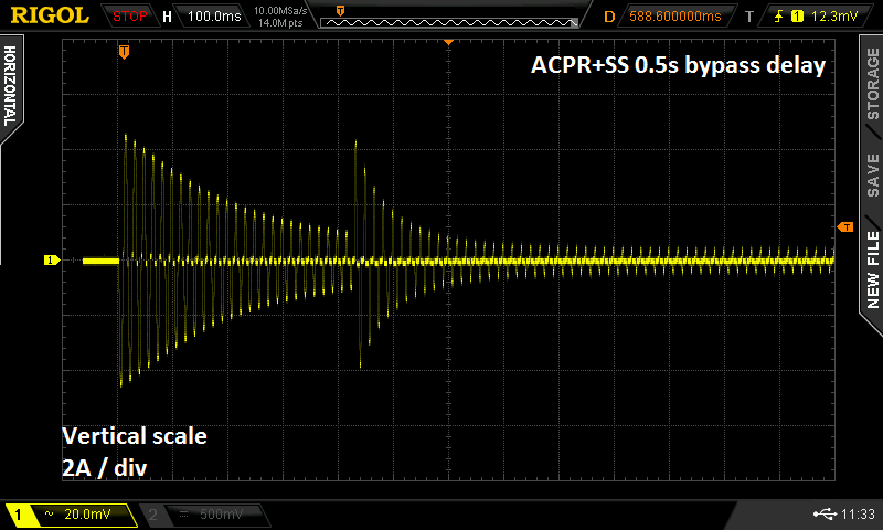
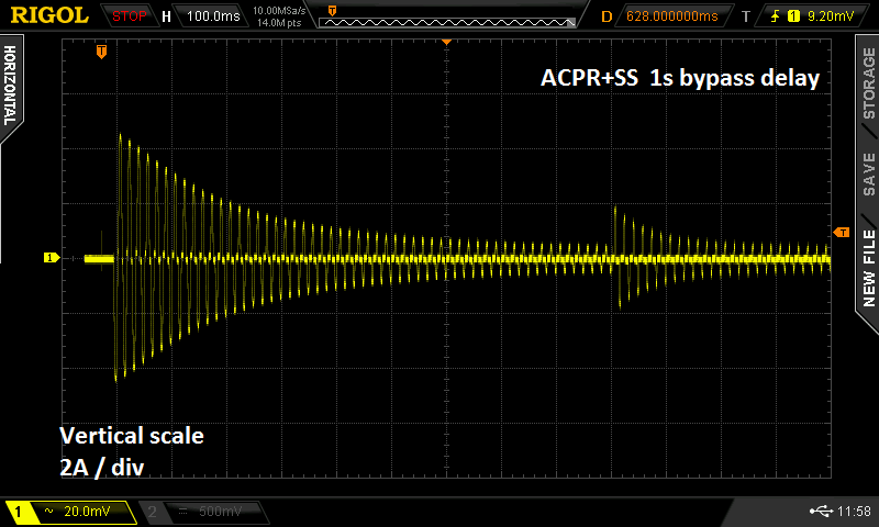
I suggest you include jumper options to adjust the delay between switch-on and softstart bypass. Here's measured data on a solid state power amp (using a current probe), at two different settings of the delay. Personally, I like the long delay better. But this choice does heat up the inrush limiting series component a lot more, since it's conducting current and dissipating power for more time.
The snubbing is important, not from an audio noise perspective as it's muted, but from a heater power voltage spike perspective.
The crossover point for the ZCD triac initial trigger is just far enough up the wave form to create about a 26mA spike which carries through that needs snubbing.
The ZCD then causes 230uA spikes on each successive waveform crossover.
Here is the ZCD triac (not the main triac) just operating by itself - although a sim using the official model for that ZCD triac, it hints at some of the noise expected and the additional snubbing required to remove the noise. Noise/spikes on this output current then cause issues for the main triac.
Snubbing an AC waveform is a PITA, you add capacitance to solve the spike, but you then cause a transition issue for the AC waveform.. So the method I'm looking at is a low pass filter configured to allow the AC rising waveform through but not the spike.
Last edited:
- Home
- Amplifiers
- Headphone Systems
- Designing my headphone amp