I may ping these folks to see if their panel meter can cope with continued 300V isolation. There is a timed test for 2.3kV between input and power.
https://br.omega.com/omegaFiles/temperature/pdf/DPPT_SERIES.pdf
I could even do a nixie bargraph tube - then simply use a reference resistor to provide the reference point for correct operation (perhaps more interesting than LEDS).
https://br.omega.com/omegaFiles/temperature/pdf/DPPT_SERIES.pdf
I could even do a nixie bargraph tube - then simply use a reference resistor to provide the reference point for correct operation (perhaps more interesting than LEDS).
Last edited:
So revising the wiring vs the heater currents now I've rationalised.
Brown - 14AWG solid copper 600V+ PTFE gives a max of 5.9A so it's not going to heat up
White - 20AWG solid copper 1000V+ PTFE for everything else with shrink-wrapped colour coded ends and at each secure point. This is probably a little over kill at a max of 1.5A but means if used on the power B+ this will not heat up.
Black - 12AWG solid copper 1000V+ (PTFE optional) ground bus. Simply to ensure a low impedance path.
Ordered some more components.
1x Hammond steel chassis
10x WIMA FKP1 0.22
4x WIMA MKPS 1uF
2x 5W 10K variable resistors for the cascodes
1x 240V 6A Schnieder combo IEC inlet, filter, fuse and switch socket.
This is enough for a single channel, and allows me some playing room. I can then fit and install components plus add some wiring and start experimenting.
I still need to source a UK transformer or two for the power.
An interesting side thread appeared in the tubes forum, what is interesting about that design is one of the 'side' elements - using a BH7 to servo balance the driver outputs by controlling each driver B+. Thread here: Kiebert Amplifiers
This would work for the driver section - essentially making the 12Bh7A anode feed into another 12BH7, but rather than being a discrete CCS it's linked to maintain balance of the drive phase signal into the backend. This would add an additional two 12BH7As tubes (one tube for each channel). Something to think about as an upgrade perhaps, but not for now.
Currently the driver section is running 320 to 0V, and the 12BH7a in the cascode are running about 150V across each tube triode section. This may work without a change given we're running cathode output without changing the ground to a B-. Figure 12 here: https://i.pinimg.com/originals/85/3e/07/853e07d08bf007214ca6f899dd498802.jpg from that thread.
So with the Frankenstein prototyping chassis which comes with a free Fedex dent but that would have resulting in long delays and my caps were in the same package. The dent is on the back side so I'll just hammer it out when I do the metalwork.
I've laid out the same (8.5" width x 9" depth) tape out as the oven sheet.
AA battery for reference.

3D construction potential is high.

The caps have short pins but to be honest they're too heavy to really support their weight by wrapping long leads around bars. You can order longer pins (the MKPs have longer pins but only by about 1.5x).
I also took the opportunity to put the caps in a circuit to decouple the signal so I could listen to them through the headphones, the following surjective observations - using sounds I know very well - guitar and rock. Metallica "Broken, Beat & Scarred". An intense combination of sounds but key here is the muting and guitar picking which demonstrates clarity on most systems, you can't even hear this correctly if you listen on YouTube for example vs the CD.
CD player in use Myryad MC100 - a solid state class A output equipped player (inside this uses muse caps too). Not high end but not a slouch at mid price bracket - presentation has been described as 'polite' but clear. I originally auditioned this with Puccini opera covering Mm Butterfly and many more, the female vocals are stunning.
This is without an amp as the CD player has enough output power to drive the 104dB/1V headphones hence the short time of listening. I'm comparing this to listening direct to the line in but I don't want to overload the output section and the impedance matching requires something in between.
Safe to say the resulting undecoupled sound is loud and extremely details - you can hear the pick on the string as it chugs..
First up a single Nichicon 330uF ES MUSE bipolar only.
First response is the degree of slam, deep sound but with an attenuated upper mid and treble. The result is some 'murk' without the required treble .
Next a WIMA 0.22 uF FKP1 only
Bejesus fast. Naturally with the 0.22 it gives the upper registers only, resulting in the missing mids and upper treble. Akin to disconnecting the woofer in a 3 way. Very fast transients compared to the Nichicon bipolar.
In the main amp, this will be paralleled 0.22uF so it will give deeper sound still.
Mixing a 330uF bi-polar + FKP1 as a taste of the output caps of the amp.
Think I may like this.. the sound is detailed and has an appropriate amount of slam, the only thing is this will sound different once in place and over longer listening to a wider range of music (I have everything from opera, female soul to heavy metal).
The WIMA 1uF MKP10.
In the amp this provides output stage grid, bypassed by a 0.22 FKP to provide much oomph to drive the paralleled output stages.
Listening to this after the above steps, this is not as clear as the FKP1 nor as deep as the 330uF (unsurprising). So initial impression is a little disappointing as I noted some murk and distortion which may be down to the current delivery being higher. I will keep an eye on that and design the installation to make it so I could possibly change the caps in the longer term.
Lastly you can see the large combined IEC socket, one thing that I didn't see before when ordering this is it has a 120/240 selector built in (hence the five connector tags).
The last thing is the earth Lug is welded to the case as well as feed thing through internally to the earth pin, so it provides shielding.
I've laid out the same (8.5" width x 9" depth) tape out as the oven sheet.
AA battery for reference.
3D construction potential is high.
The caps have short pins but to be honest they're too heavy to really support their weight by wrapping long leads around bars. You can order longer pins (the MKPs have longer pins but only by about 1.5x).
I also took the opportunity to put the caps in a circuit to decouple the signal so I could listen to them through the headphones, the following surjective observations - using sounds I know very well - guitar and rock. Metallica "Broken, Beat & Scarred". An intense combination of sounds but key here is the muting and guitar picking which demonstrates clarity on most systems, you can't even hear this correctly if you listen on YouTube for example vs the CD.
CD player in use Myryad MC100 - a solid state class A output equipped player (inside this uses muse caps too). Not high end but not a slouch at mid price bracket - presentation has been described as 'polite' but clear. I originally auditioned this with Puccini opera covering Mm Butterfly and many more, the female vocals are stunning.
This is without an amp as the CD player has enough output power to drive the 104dB/1V headphones hence the short time of listening. I'm comparing this to listening direct to the line in but I don't want to overload the output section and the impedance matching requires something in between.
Safe to say the resulting undecoupled sound is loud and extremely details - you can hear the pick on the string as it chugs..
First up a single Nichicon 330uF ES MUSE bipolar only.
First response is the degree of slam, deep sound but with an attenuated upper mid and treble. The result is some 'murk' without the required treble .
Next a WIMA 0.22 uF FKP1 only
Bejesus fast. Naturally with the 0.22 it gives the upper registers only, resulting in the missing mids and upper treble. Akin to disconnecting the woofer in a 3 way. Very fast transients compared to the Nichicon bipolar.
In the main amp, this will be paralleled 0.22uF so it will give deeper sound still.
Mixing a 330uF bi-polar + FKP1 as a taste of the output caps of the amp.
Think I may like this.. the sound is detailed and has an appropriate amount of slam, the only thing is this will sound different once in place and over longer listening to a wider range of music (I have everything from opera, female soul to heavy metal).
The WIMA 1uF MKP10.
In the amp this provides output stage grid, bypassed by a 0.22 FKP to provide much oomph to drive the paralleled output stages.
Listening to this after the above steps, this is not as clear as the FKP1 nor as deep as the 330uF (unsurprising). So initial impression is a little disappointing as I noted some murk and distortion which may be down to the current delivery being higher. I will keep an eye on that and design the installation to make it so I could possibly change the caps in the longer term.
Lastly you can see the large combined IEC socket, one thing that I didn't see before when ordering this is it has a 120/240 selector built in (hence the five connector tags).
The last thing is the earth Lug is welded to the case as well as feed thing through internally to the earth pin, so it provides shielding.
Last edited:
Next step is modelling a power supply and then essentially stepping back so I have a good picture of the power transformer required. I've played with the previously but given this is a headphone amp, there's a couple of options here:
Option 1 - use large caps and large resistors to reduce Vripple.
Option 2 - use a pair of 1.5H 400V inductors with smaller caps to reduce ripple.
Option 3 - use a madia style regulator with a basic form of the above.
In the past I've gone all out on the cap & resistor in models with a lovely 6700uF of capacitance. Just to put that in perspective - that's a good £100+ for a capacitor. Now I have a couple of supplies - one to supply 320V and one at 200V. Ego, other options may be just as good. The issue with inrush with that sized capacitance is a problem which results in ++£.
Next up is inductors (chokes). I've played with these for SMPS but not in the same vain as full on linear chokes. A simple pair of 1.5H 400V inductors can give a reasonable result - in the 200uV with a 47uF and a couple of 350uF (about £5 each). A 1.5H choke is basically about £15-20 each.
Going the active route is good - 20V drop with good performance returns, only issue is that I need both positive and negative rails with the cascodes and the push pull stages both going across from B- to B+.
In the ideal world the power supply and the PSRR would work together to reduce output. With 1 volt output (ie 104dBv headphones), we're looking at trying to minimise power supply to low Vripple if possible and then even using some PSRR to remove the remainder.
As an example 2.9µv would be -110.7dBv (Vacuum Tube Power Supply Design). Whereas 200uV is ~-80dB. It seems looking at tables that 1uV is -120dB. Although this is a tube amp it's also very close to your ear, so I'm happy togo with something like the 1.5H inductors then look at options for lowering that even more, perhaps building in some PSRR.
Now I need the time to sit down and do some calculations by hand and then compare with the ltspice.
Last edited:
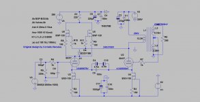
Not the right values or a usable power supply but this is the outline of what I'm thinking for a regulated B+ & B- with two postive regulators:

Taken with a pinch of salt (the regulator is a 30V piece - this will be adjusted for a maida regulator when I have the chance. The current flow is between the two secondaries (this is a concern as they would have to be perfectly matched in order not to suffer any ill effects).
LTspice shows an almost immeasurable 3.2 uV ripple. I would take that with a grain of salt.
Unfortunately it's going to be this evening before I can experiment further.. more pond building work today.
With virtually no reply , this headphones amp is definitely yours by all means ")
The real cause for people not feeling the need to get involved in your topic is that it is going to be way too expensive for the real beneffit and you still won't be able to feel a transformer-tube magic after all that work.Good design never looks at impressing the audience. I have hundreds of expensive tubes, but i stopped using them just for the sake of a warm space.Besides climate change seems real to me...
The real cause for people not feeling the need to get involved in your topic is that it is going to be way too expensive for the real beneffit and you still won't be able to feel a transformer-tube magic after all that work.Good design never looks at impressing the audience. I have hundreds of expensive tubes, but i stopped using them just for the sake of a warm space.Besides climate change seems real to me...
Up until three years ago i built all sorts of OTL headphone amps, but nothing could beat a much simpler transformer design in both sound and efficiency.I called it Teardrop headphones amp because the first time i heard it i almost felt crying at the expense of a mere 5.5ma idle current per tube. .
Attachments
Last edited:
It is possible to probably get the same with a folded/shunt cascode with a SS CCS. It has been a learning experience and I recognise the power/efficiency saving with a OPT.Everyone should build an OTL once I think also I’ve deliberately targeted non NOS tubes.
The same amp, with a little adjustment could be a 2a3 amp with a OPT with some gain changes.
I am looking at smps but you need v1 that can be built on.
Then next amp will go down the hybrid digital route.
also I’ve deliberately targeted non NOS tubes.The same amp, with a little adjustment could be a 2a3 amp with a OPT with some gain changes.
I am looking at smps but you need v1 that can be built on.
Then next amp will go down the hybrid digital route.
Last edited:

Could that psu go up to ±400v? Would be a good supply for electrostatic headphone amp.
The concept - yes.
The main thing I need to check is ensuring equal voltages on start up and shutdown.
So after all the consideration for layout.. note the edge of the red is the centre... not the middle!

I'll sort out the mounting holes tomorrow and then I can start really putting stuff inside.
I decided to move the driver tube into the centre.. no real issue with the implementation, but solves that 'missing hole' feel.
I'll sort out the mounting holes tomorrow and then I can start really putting stuff inside.
I decided to move the driver tube into the centre.. no real issue with the implementation, but solves that 'missing hole' feel.
Last edited:
Hacking away at the prototyping case..
All the V1 sockets attached - I can now start really installing bits inside..

I will have to get myself a few more tubes... In the original single ended configuration..

However this is what V1 will look like.

The pond project is the first priority, this is second but we're getting there..
I found my yellow/green solid wire is 1.3mm diameter.. so way thick enough for heater wire Plan is now that yellow/green twisted is heaters rather than using brown.
All the V1 sockets attached - I can now start really installing bits inside..
I will have to get myself a few more tubes... In the original single ended configuration..
However this is what V1 will look like.
The pond project is the first priority, this is second but we're getting there..
I found my yellow/green solid wire is 1.3mm diameter.. so way thick enough for heater wire
Plan is now that yellow/green twisted is heaters rather than using brown.
Last edited:

Just been sorting out the power transformers and inductors.
Unfortunately Terry (Cantebury Windings) isn't taking on new work for 2 months.
I thought about Toroidy in Poland but they have a comment on their website for longer delays for orders given the current copper issues.
So I had a chat with Stephen at Tiger Transformers today. This looks very promising. I've also over specced the transformers to allow me to use them for other project prototypes (ie the RF tube digital amp).
These will be wound on over sized cores, with insulation and banding, but I will have two separate transformers for the B+ (each having two isolated secondaries to work with the regulators).
He also had a good solution for the heater supplies too and I should find out about the 9H chokes later this week.
They're custom but they don't break the bank. I'll confirm everything later this week and then put an order in.
I've been having a listen to one of the output pair capacitor blocks, directly from the CD player. Some noticeable points:
1. The CD player line-level is starting to find it hard to drive, leading to some additional distortion. I don't have a resistor or volume thus the CD player is seeing through the 4x330uF+0.22uF the low impedance not the high impedance input stage of the next section as it would have been designed for.
2. The sound is fast and has punch/slam in the deep bass however give point 1 it's not as clear as I'm expecting the final amp to be (with 4 of these sections per channel, each being driven separately).
As the pond is pending a few bits, I currently have some time, so I may knock up the remaining modules. So I may have chance to finish the transformer modelling.
Also I decided I would go with point to point rather than use a PCB board. Probably not the long term solution but I decided to point-to-point everything for this amp.
- Home
- Amplifiers
- Headphone Systems
- Designing my headphone amp