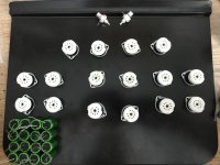
So I've been a little busy at the moment.
So the amp has morphed a little in complexity.. so I'm now focusing on each section
1. Frontend is now more complex (for audio reasons) however this is classic class A differential so I'm happy to proceed with this. However it requires bi rails of 320V. This bi-rail requirement kills off my initial idea of running the frontend from the simple boost converter I had planned. Instead a we need an isolated FE power supply - so something with 320V+ and 320V- is in order. Luckily that's not too bad from a current perspective - the front cascode is 20mA max and the differential after is 40mA. For each channel I should add. Each valve has about 150V across it.
2. Output section - I have the option of running a simple OTL output stage initially. This is the current monster and the main reason for developing the power supply booster idea and also the idea around fore-going and simply implementing a tube modulated power supply (ie a tube switched output stage) this idea simply seems to satisfy the longer term goals.. but for now I think I may go for a class A mosfet follower.
The PP OTL stage would need ±200V rails which again complicates the SMPS output concept.
3. So this got me thinking about moving away from the 48V->rail voltage boost and thinking about a more modular flexible system - it also allows the PSU to be tailored. It may sound complex but in reality they're almost the same thing, just tuned differently (except the PFC stage).
* Active power factor converter ~100-200Khz switch rate for audio specifically this would provide around 300W of power corrected 390Vdc power. The idea could support higher power and easily could provide high current - this would for this reason use a PFC IC and mosfets. Simply put they are the best solution for the job.
* SMPS heater stage - 390Vdc to heater voltage outputting high current but isolated so that the supply can be elevated if required to maintain Vhk limits. Using this straight off the same PFC has a benefit that the PFC is constantly loaded so we don't drop into a low load situation.
* SMPS FE power - supplying +320V and -320V regulated power from 390Vdc input. Again high speed switching and filtering and this has to isolated to allow the ground reference.
For the short term an identical 200V variant could be made to drive the output PP stages initiailly but it's also easy to simply run a LPF in the supply to drop the voltage.. If need be a duplicate could be made and then re-used to have a power supply for each channel.
* SMPS switching output stage - switching of 390Vdc to the output signal, sort of implementing Class-D in valves. Again running at 100-200kHz means the noise should be filterable, leaving the signal from the class A input stage alone. This stage could be tuned for headphones or speakers.
So this is looking like a plan. The components I've bought already fit in to this (including the SMPS inductors I was using as a boost inductor are actually 400V+ capable differential inductors).
So I've been researching PFC with a focus on noise, harmonics, and subharmonics.
<150W DCM generates noise due to the drop to zero (I found this before when looking at them)
150-250W CrCM (TM/BCM)
250W then CCM becomes the order of the day for higher power and lower noise. My boost controller I was looking at before was CCM for this reason.
So most PFCs are basically a boost converter. The key here is that if we don't want harmonics then we must ensure our output voltage is above the input rectified AC voltage.
I've looked at interleaved boost controllers too before, and in fact you have the option of parallel or interleaved PFC for more power.
With an eye on the heater requirement meaning about 30W-50W that means at 10% we should be in the 300-500W PFC bracket.
Next up is the switching - the UCC28180 is a CCM programmable frequency PFC controller that can switch up to 250kHz. There's also the UCC28070 that's a CCM two phase interleaved PFC controller too.
The CCM topology has one major difficulty and that's the reverse recovery loss from the diode. That can supposedly account for 20-40% loss so a SiC ultra-fast recovery diode is required.
The pspice model for the UCC is flawed as it doesn't fully model the current handling so you don't see the proper waveform back to the AC. Also it's been going since 2009 so I may continue to have a look at more modern options.
The majority of the Onsemi NCP range CCM ICs are only 100kHz switching, although the NCP1654 does do 200kHz.
The L6562 and L6599 are transition mode (CrCM) so those aren't first choice.
So for now it looks like a 300W CCM PFC (probably non-interleaved) is the way to go.
This is a great centre point for topologies: https://www.ti.com/seclit/ug/slyu036/slyu036.pdf
I found a couple of interesting points on the EMI noise aspect - I'm specifically researching noise and EMI:
https://vtechworks.lib.vt.edu/bitstream/handle/10919/73166/Wang_Z_D_2016.pdf?sequence=2
This has some very interesting stats in terms of caparisons and component losses. It also shows that Gan-MOSFETs etc are possibly the way to go for efficiency due to their extremely fast switching as the losses are in the terminal capacitance of the mosfet etc and the use of ultrafast diodes with little or no reverse recovery losses.
Given we want to push 100-200kHz to shift the noise above the audio spectrum it's also worth noting the impact of non-fixed frequency that can put noise into the t/4 area so keeping to 200kHz means even if the chip does use frequency changing to manage the load better, it's only going to make noise at 50kHz, but it does make our filtering harder.
The CCM PFC is essentially a boost converter but focused on current shaping so this follows my boost converter work quite nicely. As a booster we must have a Vout>Vin and we should have 10%+ load as a general rule or we'll have sub-harmonics as extra noise, plus sub-harmonics creates a lot of coil squeal/whine which is not something we want from our PSU is it..
Another paper I found detailed the use of a second winding on the inductor to provide EMI noise cancellation. Almost like a common choke as the inductor. That can be found here: Noise Cancellation for Miniaturization of Switched Mode Power Supply | OMRON TECHNICS | Technology | OMRON Global
Worth exploring in ltspice..
Interesting that this piece seems to show Cuk topology being the lowest noise: Ampersand - Wikipedia
Last edited:
A nice paper on Cuk PFC: https://www.ijert.org/research/anal...r-correction-applications-IJERTV3IS051862.pdf however it does only look at DCM so <300W but then also represents a noisy implementation.
I'll keep looking for a CCM version but it's not that far away from the DCM (just the configuration so the inductor never intersects with zero).
I'll keep looking for a CCM version but it's not that far away from the DCM (just the configuration so the inductor never intersects with zero).
Last edited:
So after a lot of playing with the idea of a tube powered SMPS itself, including modelling the logic of the IC chips in ltspice, the key issue has come back to haunt - current.
In the end a valve is low current high voltage unless it's a large power application but typically these have massive requirements themselves. Heater supplies take more power than a valve can supply as a switching component in an isolated SMPS. So I will keep the solid state for the PFC and for the power supplies in general. The efficiency, the choice of parts and the general fit really warrant that.
The power stages will then have suitable isolated supplies from the DC link, and the most suitable given very low ripple is the Cuk and provide common noise on the positive and negative rails for noise rejection. This also allows elevated heaters in a supply for the frontend for example.
Next up is the output stage. I've looked at a number of options here using the valves as a switcher - this, regardless of the switch or analogue approach, needs current.
I've looked at analogue topologies and at digital switching at high speed - PWM, PDM, DSD and even quadrature. It's apparent that the more resolution (ie digital and analogue being the highest), the more the tubes need matching.
A DDS style 1 bit high speed is a great example of what can be done - sampling and then simply applying the binary switching via the output valves. The down side is careful selection of the valves to be able to cope with the rate of switching - DSD512 is in the MHz region which means power valves with very high voltage to get the required transition speed in a clean manner.
What is attractive about a 1bit parallel valve output stage is that the tube only has to support the voltage for ON and the voltage for OFF. This makes the resulting tube support easier for parallel tube matching. The down side is that the tubes need to be shielded.
So it's lucky this is a headphone amp - as it offers that opportunity to implement something 'different' as the power needed is relatively low for 32ohm high efficiency.
So my current thinking is having an analogue a class front end and then have a digital output backend with the tube ADC and the amplified signal being a tube digital switched signal with a filter on the back. This then can support DSD512 directly. I suspect the option will also be that you could simply plug the input into the ADC directly and forego the a class front end but where's the fun in that.
So my next focus point is the ADC and output switching that is compatible with DSD. The pulse density can be done with a voltage controlled oscillator and a schmitt trigger. It's possibly not much of a step from that to DSD - I'll need to mock something up in ltspice.
The question is - do I do this directly on the 390V DC link power rail and then signal switch, filter, through an isolating high frequency transformer (this is above the audio spectrum) and final filtering. Alternatively an isolating power stage with a standard SMPS transformer for the power then the output signal switching stage through an output cap.
Hmm I think that will be my next investigation.
So.. version 1. I still have the V2 tube-direct digital amp/hpa in design but circling back for v1.. I've taken some of the learnings from the design work for the direct digital amp, specifically the bode plot and focusing on the bandwidth and phase - this is why it has caps in parallel for example.
The design originally started with the Broskie (tubecad) single ended OTL headphone amp class A, this is a decent design but modelling showed a few little gotchas for inputs with over 1V, plus I'm not very keen on the 12AU7 thus the change for the more linear 12BH7A. However I wasn't too happy and low and behold the atmosphere M60 seemed like an interesting design.. so modelling showed it's very clear benefits (at the cost of more tubes) and thus the hybrid Atmosphere M60-Broskie OTL HPA (now in PP format) appeared:
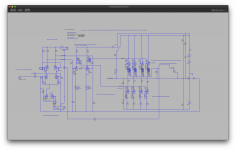
Each channel has four 12BH7As on the front end and four ecc99s on the backend. (note: minor correction the 0.1F should be 0.1uF and with a 5-10uF also in parallel)
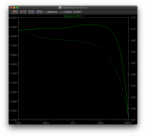
Bode plot at the output shows the amp's bandwidth.. VHF anyone?
And the output power into 55 ohms but it's equally happy driving 32 ohms from the sims:
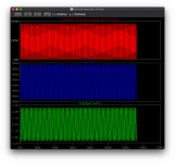
There is a piece of work to tune for 3rd harmonics reduction which all come from the untuned ecc99 backend and selectively adding in LPF grid stoppers to prevent the amp from going into HF/VHF meltdown. The output here is with 1.5V 1kHz input:
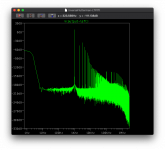
So some twiddling required but I suspect that will reduce.
The design originally started with the Broskie (tubecad) single ended OTL headphone amp class A, this is a decent design but modelling showed a few little gotchas for inputs with over 1V, plus I'm not very keen on the 12AU7 thus the change for the more linear 12BH7A. However I wasn't too happy and low and behold the atmosphere M60 seemed like an interesting design.. so modelling showed it's very clear benefits (at the cost of more tubes) and thus the hybrid Atmosphere M60-Broskie OTL HPA (now in PP format) appeared:

Each channel has four 12BH7As on the front end and four ecc99s on the backend. (note: minor correction the 0.1F should be 0.1uF and with a 5-10uF also in parallel)
Bode plot at the output shows the amp's bandwidth.. VHF anyone?

And the output power into 55 ohms but it's equally happy driving 32 ohms from the sims:

There is a piece of work to tune for 3rd harmonics reduction which all come from the untuned ecc99 backend and selectively adding in LPF grid stoppers to prevent the amp from going into HF/VHF meltdown. The output here is with 1.5V 1kHz input:

So some twiddling required but I suspect that will reduce.
Last edited:
I should also make the point that looking back on the M60 front end I can also see why the benefits appear.
* differential from the start - why not, this presents a good opportunity for PSRR but at the same time normal cascode PSRR is pretty poor. It also allows both single-ended and balanced input which is a nice to have.
* the cascade reduces the miller effect on the first input tube increasing bandwidth. The gotcha is the high output impedance, elevated heater requirements and bigger B+/B- rails on the front end. The single pair of drivers is required for this reason - in the normal design the output is taken from the low impedance cathode side, typically because the tubes used (6sn7) support a good transconductance and maintain a higher gain over all. The 12BH7As aren't like that so we switch to use the higher impedance but higher gain anode side output. However they do have enough oomph to drive the ec99s without throwing their toys out of the pram - this means they can drive the reasonably high capacitance.
ecc99s well they're uncouth driver beasts. You could switch those drivers to be ecc99s if you wanted more current to drive.
* Now comes the interesting point - the M60 uses a feedback into the driver ground stage rather than the front end. This works but on the bode plots shows a marked impact on the gain linearity between the two phases used to feed the push-pull.
The approach does remove a large amount of harmonics, perhaps correcting overall in sound and making up for the difference in phase gain. Perhaps there's some tweaking of the grids to address that. Worth exploring with a soldering iron and a screwdriver.
* B+/B- means, with the right supply (ie common mode noise being on both) design that this helps cancel noise out.
Powering the amp.. I'm considering a SMPS based approach, it's a little split between the 40mA@±320 and 200mA@±200V per channel and then heaters on top. The benefit of using SMPS is the components should be reusable/transferrable to the direct digital amp/hpa.
So with a PFC providing 390-400V DC on a DC link bus, other modular adaptors can then reformat the power to the right form, for example a Cuk with regenerative power stage. The secondary stage is then isolated - providing both +200V and -200V for example. The next step would be to isolate the voltage feedback line..
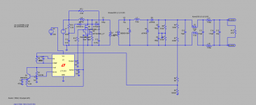
A second module could then connect to the same 390-400Vdc bus and provide +320 and -320. The only difference would be the components and the voltage setting.

A second module could then connect to the same 390-400Vdc bus and provide +320 and -320. The only difference would be the components and the voltage setting.
So V1 is progressing as I can. I've been looking through the different options (mallory, sprague, Panasonic, Wima, Mcap, auricap, etc).
I will be using the following given I have a number in parallel the prices can/do mount up quickly hence going for an option that is likely to be more reliable:
* Panasonic ECW series for decoupling 0.1uF and 10uF - these will be 630V and 800V pieces - this means the AC Vpp can be 250V and 400V respectively.
* Nichicon ES MUSE for the 330uF output - yes these are 50V but I will have a 600W 25V TVS with a crowbar protection on the output. These are bi-polar electrolytics. Modelling has shown this doesn't get above this. Each output tube has it's own 4x330uF output - that's 32 caps in total
In other news the V1 will have a linear PSU in the spirt of KISS (keep it super simple).. as simple as the complication can be.
Both linear and SMPS transformers are a PITA to get one done right.. and linear results in an easier implementation in the short term - I want an amp done by the end of the year (current shortages and Brexit make this a challenge).
I stumbled across this video on YouTube - building an M60: Making the Atma-Sphere M-60 - YouTube
My version of this doesn't use a cyclotron design, but a simpler PP OTL design (16 B9A tubes total) . However there's a couple of interesting observations I can adopt:
1. Noise layout
Look at the layout and you can see the focus on noise reduction. transformers on top. rectifiers in the furthest corners, and caps making a central 'quiet corridor'.
Decoupling bypass caps sit at the back behind the cascode.. away from the power section.
The input cascode is the centre - far away from the power (although the AC heater passes close). The front tube houses the driver triodes.
Output sections front sides - well away from the input section.
2. AC heater crossing is at 90deg to the sensitive wiring.
3. decoupling caps between the cascode and drivers sit straight and away from noise but are the reason there's space between the cascode and driver.
The wiring is solid (given it holds shape) and sits cleanly - held in 3D by some standoffs and the tag boards.
Some inspiration - I was just doing the chassis plan.. so this has some interesting lessons.
Mine will look a little different.
Power in the corners - I like this. I will NOT pull the power to the front for a switch - instead a power switch at the back but a push-on 5V to the front. This will trip the power start.
Input / Cascode I will have two sets (left and right channel) in the centre. They will be in an L shape.
Volume control is an interesting one - I could pull it to the front but this complicates the noise.. so perhaps volume close to the cascode but with a connector rod.
Output sections will be a block left and right for the channels - with the output caps being at the front left/right of the chassis for each channel.
I will have the output jack at the front.
Power - I'm currently eyeing up Toroidy for the power transformer(s) and I may see the cost for creating a bespoke combined 320-0-320 & 200-0-200. I will need three heater supplies as they need elevation and dropping (the tubes have a 100-200V limit between heater and cathode).
The nice approach here is that the sections are modular. The wiring, as point-to-point, is clean. This pushes my OCD buttons.
I'm also considering a hammond case with a protective mesh. Given the number of tubes and the 600V+ across the input section, perhaps the idea of a wood based amp is not such a good idea - heat in the chassis and safety of not so exposed tubes may be a good idea.
Last edited:
I've actually switched the Panasonic caps for WIMA FKP 630V 5%. These are PP with metal foil with the FKP1 having a serially connected plastic metabolised film with the result is their rise time supported is higher than the FKP4. The FKP2 & 3 are straight metal foil. The MKP are vacuum deposited metalised plastic film thus are smaller but less current capacity.
How much difference is that sonically? Not much. However given they're a off the shelf.
How much difference is that sonically? Not much. However given they're a off the shelf.
Looking at resistors.
So looking at distortion, noise, inductance and thermal stability..
For noise and distortion vs frequency:
High noise
* Carbon variable trimmer
* Carbon Composition
* Carbon film
* Metal Oxide
* Wire Wound
* Metal Oxide
* Metal Film
* Metal Foil
Low noise
High Inductance
* Wire Wound
* Carbon / metal film / metal oxide spiral wound
* Carbon variable trimmer
* Carbon Composition
Low Inductance
https://pub.dega-akustik.de/ICA2019/data/articles/001261.pdf
So the metal film is also the most expensive but provides a the lowest current noise, and the most stability vs temperature. However we're talking about $$ per resistor vs cents.
So it looks like MOX or Metal film rather than metal foil.
Just been playing with the final model tuning - I found a bug in the LTSpice model (a copied label between the channels added recently).
So far I've had this modelled at 0dB as a unity buffer and now modelled with 3.16V input giving about 2W with 16Vpp at ±240mA max output (8dB gain) - enough to fry headphones (the tubes output maxed out) with some NFB.
The amp's purpose isn't to be a gain monster but it shows that the front end can be tuned. I could switch out the 12BH7A for something with more than 17 mu but this will do.
So I'm happy with the capability and how easy it can be tuned.
Switching to paper cut outs I’m targeting a 17” wide, 14” long and 5” deep.
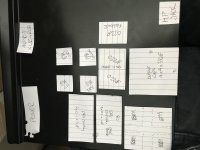
The pan is smaller, but large enough to model the front end. The jack is in the centre of the target case.
I’m attempting to ensure that the power corner is kept clear and attempting to get the large PP film caps in between the tubes.

The pan is smaller, but large enough to model the front end. The jack is in the centre of the target case.
I’m attempting to ensure that the power corner is kept clear and attempting to get the large PP film caps in between the tubes.
Current layout state of play
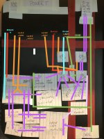
I've rotated the pan 90deg as this gives me 14" depth, I can then mark out the three red lines of - the centre line of the amp (at 8.5" wide) and then the 9" inc from the back where a hammond mesh box could sit across the amp. Behind that line is where an upper box sits that holds the vertically mounted transformer and smoothing caps.
The last red tape line is the 'quiet corridor' where large current flow and higher voltage lines are kept away from.
The red lines are the B+ lines, the cool-blue are the B- lines. The orange shows the heater lines - one at about 50V and one at about -150V to provide power - I may need another voltage level.
The violet shows the signal path flow for the both phases.
Lastly the green shows the ground line. The headphone output is for single ended (ie shared ground). If balanced output was to be used, more design work would be required - so for me this is not required.
The concept here follows:
1. the power supply is kept in the corners.
2. The input RCA, input shielded cabling, input valve and cascode sit in the quiet area.
3. The drive (DRV) valve sits just outside - this allows the power rails to be easily supplied through to the cascode.
4. The amplified output passes through the decoupling caps towards the ECC99s which sit close to the side of the case - this allows high current in wires close to the side of the case.
5. The amplified output then flows via the output caps back to the front centre.
6. The feedback is driven directly off the output caps output and then loops back via a shielded cable to the cascode.
My only concern here is that I have a large loop - as the signal return is through the centre of the amp.
In reality there's a 5" chassis depth, so I can reduce the 2D real estate by making it more 3D however that has other issues such as blocking of cooling. However I suspect that the final deployment will see the set of ecc99s move towards the centre a little.
The other point is that I have made a 'compromise' that I've switched from 3x0.1uF + 1uF for the driver coupling to simply a 1uF+0.22uF. This doesn't model much different in terms of a bode plot, it will be using the hyper fast FKP1 that has both metal foil and deposited metal plastic film in series to increase the performance (lowers ESR). Plus it reduces the size physically and with the added bonus that 0.22uF is basically the most common capacitor in the amp thus we start seeing volume cost savings being above 10 caps.
I still have to work out where I can put the variable bias pots, volume pot, muting relays.. so we're not finished yet. For example if I have the lower ecc99s closer to the back, then the dead space can be used for the bias pots.
It should also be noted that I have one input RCA or XLR balanced but a single ended output headphone jack. If I wanted to have a balanced headphone output there would need to be some additional design work (not to mention additional hardware).
Last edited:
Tracing the main DC HT electron flow (white arrows) that flow from B- (blue) to B+ (red) rather than via the 0V ground as a return:
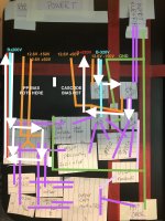
The B+/B- I'll twist together, I'm not sure I need to twist in the 0V ground used for the cascode grids.
The cascode is connected to the 0V-GND for the grids so virtually no current flows.
In terms of signal current. The cascode signal piggybacks the DC current flow until the cascode-driver decoupling cap. The cascode is kinked to keep the input DC current (from the CCS) at 90deg, the input to cascode at 180 away from the input and then the driver at 90 to keep it's output away from the output cap/headphone jack.
The main output stage drive signal currents are contained within the output tube stage and flow to the output caps.
For the build I think the output caps and bypass caps will be stacked in 3D so in reality the output signal will terminated in the corner, then shielded cable takes it to the headphone jack and feedback point. This stacking should be fine - it allows me to put space between each cap too for cooling.
The single ended headphone out means there's one common AC-signal return on the 0V-GND for the headphones.
The heater wires in the diagram are complex. Initially a AC twisted pair running 12.6V for low current noise but there are several independently referenced against the B-/B+. Not shown in the diagram but I intend to ensure they're kept shielded against the chassis as much as possible. I will probably run these as regulated DC in the future where twisting is still a benefit.
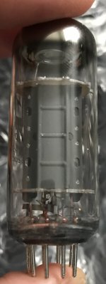
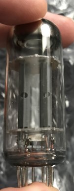
At the moment I'm considering the effect of few things. The tube geometry in terms of heat radiation given there will be a bank of 8 tubes at the back. There's a multi-way trade off here:
a) heater wires minimised as much as possible
b) minimising the signal grid connection and decoupling
c) internal radiation so that the closest tubes are only showing the smallest amount of heat radiating components - this is especially important for the input and cascode tubes. The second channel is not that far away. I could put a matt black copper screen between the two channel cascodes stacks. Heat radiation is dependant also on distance, the radiation falls at radius^2 so the more distance the less heat.


Last edited:
Next up is wiring colour codes, I may as well follow the old colour codes. So the following will be present in the amp:
UK colours standards here are:
AC-L - Brown
AC-N - Blue
AC-E - green/yellow stripe
Then within the amp:
Black - Earth bond/chassis ground
Brown - Heaters.
Red - B+
Violet - B-
Blue - Plate
Yellow - Cathode
Green - Grid
White - Bias negative supply
Gray - AC within the power supply.
Orange - N/A (screen grids for pentodes)
The danger is that people assume things - such as the brown filament being 12V.. when one will be in the region of -150V for example. Also the B+/B- lines don't differentiate between 320V and 200V, the grids - well some will be at 0V others will be close to -200V. .. the list goes on.
So this indicates the rough purpose but not the voltage level.
Last edited:
Looking at the overkill cost of cables of different colours at the moment, it would be cheaper to use white 1000V PTFE cable with coded colour heatshrink at each end and at strategic points along the runs.
I can then get 30-60 meters 22AWG rather than fork out £90 for a spool of violet alone. Solid copper 22AWG's current rating is 6 amps. More than enough.
For the heater supplies I'll then get a 18AWG brown.
I already have some PVC red, black and green/yellow but I want the entire thing running a consistent wiring. Call me OCD but..
For anyone following along at home..
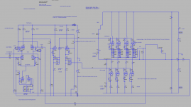
So some changes/corrections:
* The driver section was attempting 520V across.. at some point I'd switched this over when playing with PSRR. It's now 320-0 not 320-320.
* Switched the driver output to cathode (actually this is the same as the m60) as I don't need the amplification - I'll leave that to the cascode. This makes it a low impedance output into the high impedance PP grids. This also improves distortion.
* Heaters are now rationalised as: +50V and -150V to cover the entire amp - this stays within the design limits for the 12BH7A heaters ( H>K+100Vac/200Vdc and K-200Vac/dc<H) but also the ecc99s (±200V limit).
There's enough wiggle room so that adjustments on the cathode resistors for bias mA tweaking so that they don't exceed the limits - with B+ or without B+ applied, however they're referenced to the B+/B- anyway.
* Rationalisation of caps to use FKP1 0.22uF, 1uF and MUSE ES 330uF. I can adjust these to multiple 0.1uF at a later date but there's very little impact and with over 10 there's a volume discount. A MINIMUM of 630V is required given the differences between some of the decoupling.
I have found a 100mA panel meter - perhaps not the most accurate but I'm tempted to add one for biasing. An alternative is to use a three LED system to indicate when it's within a 1-2 mA of the value. More accurate options are £100+ - there's a few Hoyt meters that I like the look of too.
Only issue here is that it's unclear of the isolation voltage limit on the panel meter - it may measure a small relative difference drop across a 1ohm resistor, however that small drop is sat at -280V for the cascode.. Internally that may arc to the grounded chassis..
Lastly - for £34 I found a neat IEC+filter+switch+fuse all in one which is tempting.. Neat, tidy and being schiefer it's an OTS.
I'm currently running around looking for quotes for the transformers, the amp needs:
160-0-160 600mA - fully rectified gives 226V so enough for a regulator drop and some current wiggle room
240-0-240 100mA - fully rectified gives about 340V so enough for a regulator drop and current wiggle room
Two 12.6V supplies - these need to be referenced to +50V (3.4A min) and -150V (2.4A min) accordingly, so isolation needs to take account of AC to -150V reference. For these I will use separate heater transformers. Also the heater wiring needs to insulate between -150V and anything else around it (0V chassis or +320V B+ should it come into contact).
Wiring for this amp is not a 300V insulation jobbie.. 600V minimum between conductors and earth, preferably 1000V.
Last edited:
Complication here also for the heater supplies on start up and shutdown. It's possible to have the reference voltage on one side of any smoothing caps and 0V on the other. Therefore we can't use 50V caps but we need larger voltage caps..
For the panel meter it may be that I need to make a isolated opamp with an optical isolation.. more complication..
For the panel meter it may be that I need to make a isolated opamp with an optical isolation.. more complication..
Last edited:
- Home
- Amplifiers
- Headphone Systems
- Designing my headphone amp
