An ultra low distortion moderate power headphone amp was designed for use with a phono/line preamp project.
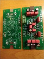
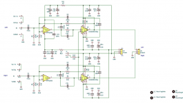
This is the stand alone amplifier board that was developed.
The goal was to provide an unbalanced headphone amp that would produce essentially unmeasurably low distortion at 2v RMS output, could drive headphones from 15-300 ohms, and would operate using the +/15v supply that was used in the preamp.
Specifications:
+/-15v - SMPS is fine. 0.6A per supply rating.
>90dB power supply rejection over the audio band.
Peak output drive current set at 270mA/channel
0.4W max into 15 ohms.
0.8W max into 30 ohms.
0.15W max into 300 ohms.
Stable into any load capacitance.
Output impedance <0.1ohms.
DC offset <2mV.
AC coupled input (0.47u PP cap, 220K ohm input resistance).
1.5Hz - 1MHz 3dB bandwidth.
Thermally protected.
Protected against shorts.
Fault LED indicating overheating condition.
PC board designed using TI guidelines to act as heatsink, and can accommodate 15ohm and higher loads without shutdown at rated power levels.
Stable into any capacitive load.
6dB gain.
10k volume pot can be added.
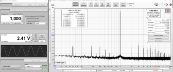
TH Distortion plus noise @1kHz, 2v RMS output 80kHz measurement bandwidth: <-114dBc (0.0002%) A weighted. Limited by measurement system.
Not appreciably different at 20kHz, not appreciably different for 30-300 ohm loads.
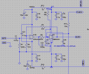
Basically a realization of the TI app note with simulated/evaluated compensation.
This is the stand alone amplifier board that was developed.
The goal was to provide an unbalanced headphone amp that would produce essentially unmeasurably low distortion at 2v RMS output, could drive headphones from 15-300 ohms, and would operate using the +/15v supply that was used in the preamp.
Specifications:
+/-15v - SMPS is fine. 0.6A per supply rating.
>90dB power supply rejection over the audio band.
Peak output drive current set at 270mA/channel
0.4W max into 15 ohms.
0.8W max into 30 ohms.
0.15W max into 300 ohms.
Stable into any load capacitance.
Output impedance <0.1ohms.
DC offset <2mV.
AC coupled input (0.47u PP cap, 220K ohm input resistance).
1.5Hz - 1MHz 3dB bandwidth.
Thermally protected.
Protected against shorts.
Fault LED indicating overheating condition.
PC board designed using TI guidelines to act as heatsink, and can accommodate 15ohm and higher loads without shutdown at rated power levels.
Stable into any capacitive load.
6dB gain.
10k volume pot can be added.
TH Distortion plus noise @1kHz, 2v RMS output 80kHz measurement bandwidth: <-114dBc (0.0002%) A weighted. Limited by measurement system.
Not appreciably different at 20kHz, not appreciably different for 30-300 ohm loads.
Basically a realization of the TI app note with simulated/evaluated compensation.
Attachments
The goal was to provide an unbalanced headphone amp that would produce essentially unmeasurably low distortion
Ok, good!
But let me a pair questions:
1. Why compensated opamp?
2. Why noninverting?
1. Why compensated?
My guess is that you have some kind of unspecified POV in this that prompts the question.
Nevertheless, here goes.
Generally all opamps are internally compensated- otherwise it's hard to ensure stability in general use. Sometimes the compensation is for unity gain, sometimes not.
What really matters is the level of feedback factor at whatever the closed loop gain is, and whether or not there is sufficient phase margin at that gain to ensure stable operation, particularly into difficult loads that cause additional phase shift at the output.
Having a sufficient feedback factor ensures that the input signal at the frequency of interest is sufficiently small to keep the input stage generated distortion small, and also works to reduce the higher order distortion products generated by the input non-linearity acting upon the amp output distortion that is being fed back to the input stage. It also acts to reduce the intrinsic open loop distortion of the output buffer (The LMH6321) It also helps to ensure that the PSRR of The system is maintained up to acceptable levels at the high end of the operating frequency range, including acting to improve the rather poor PSRR of the LMH6321.
The OPA1656 has a high unity GBW product- 20+MHz, and a somewhat more sophisticated than just-a-plain-integrator compensation scheme that allows the effective GBW product at audio frequencies to be higher- c. 53MHz, which allows for higher feedback factors to occur, which is beneficial.
The OPA1656 also seems to have pretty low intrinsic distortion- presumably because of the fet input stage.
In fact, compensating the closed loop composite amp was straight forward. In essence just the buffer 10k protection R was problematic. I tried two stabilization techniques, including effectively closing the loop separately around the input opamp and applying lead compensation in the feedback path, as well as putting a shunt cap (internal lead compensation) around the problematic R. Both techniques worked- separately but not together- and the bypass around the problematic R approach seemed to be stable into any load I threw at it (including some extreme cap values and open circuit load Rs) and it allowed the full feedback factor to be employed to reduce the buffer distortion- so it was chosen. It was initially simulated using TIs macro models and then bench tested for stability and distortion versus estimates based on the data sheets of the two devices as a starting point for the calculations.
2. Why non inverting?
I wanted to maintain a high input impedance to permit easy AC coupling with a reasonably cheap PP cap. I wanted to not have the noise generated by the large Rs. I wanted to operate in a 6dB gain mode, so it was straight forward. I didn't see any additional distortion products due to the common mode signal appearing at the opamp input. I didn't see any problem with square wave or clipping performance into any of the loads I tested. The many tone tests were exemplary. The input is MOSFET so common mode input bias currents were not problematic. I wanted to be able to use an external volume control that would not alter the input loading too much and would have a reasonable taper.
Indeed I saw no reason for it not to be non-inverting. Perhaps there are things that I'm missing.
I really don't know how well the amp performs. Only into a load of 15 ohms at high power levels did I measure a result that deviated from the loopback performance of my test platform- an RME ADI-2 PRO FS R, and that by only a miniscule amount- c.1 dB in a SINAD of c.114dB.
Yes, I contemplated using OPA1622s- essentially two duals per channel- three amps in parallel with the fourth as an input stage.
The major reason for not doing that was was solderability. The fine pitch package of the OPA1622 was considered, by me and others that I asked, to be too daunting a task for the home DIY'r, whereas the OPA1656 in the SOIC package and LMH6321 in the DPAK/TO-263 package were quite doable and the calculated performance based on extrapolating the data sheet distortion curves etc. and estimating the result after applying the OPA1656 feedback factor in a x2 mode seemed excellent.
The hardest part was designing the "heat sink" into the board and estimating the thermal properties so that the output power goals could be met without thermal shutdown occurring.
The compensation was also uncertain, but the models were surprisingly accurate.
Here is the Mouser cart:
Mouser Electronics
Note that this does not include the power supply. A +/-15v >=600mA per side supply is needed for full performance, although 9v batteries can be used at lower power. This can be a separate SMPS, a pair of 15v wall warts socketed in series, or a linear supply.
The following DiyAudio thread shows the board in use in the prototype phono/line preamp.
Ultra high spec. opamp MC/MM phono, warp "elliptic" filter, line, headphone amps.
Post #19.
Last edited:
PM sent, cheers.Yes, a few boards are available at cost plus shipping.
Please PM me.
What really matters is the level of feedback factor at whatever the closed loop gain is
Clearly!
And using some of the Av>=10 opamps like AD8067, LM7171, THS4021, LT1222 allow you to pick additional 10-16 dB of such a feedback. The can be easily compensated for lower gains externally.
I wanted to maintain a high input impedance to permit easy AC coupling with a reasonably cheap PP cap.
Most of the modern sources can be DC-coupled and in case of 2k input impedance such a headamp can be easily connected through 10k linear potz and provide you with a perfect logarithmic volreg.
I didn't see any additional distortion products due to the common mode signal appearing at the opamp input.
Common mode error are nonlinear with common mode itself and doesn't specitied in most of datasheets.. So why add nonlinearity while you can't?
Yes, I'm well aware of the possibility of using opamps internally compensated for higher closed loop gains and externally compensating them- I actually designed such opamps for ADI in the 80's.
I expected that this is where the question would lead. I would assume that you have ground this axe before.
In any case, I wished to avoid the potential complexities of trying to compensate a classically tricky situation- composite amp, arbitrary capacitive and resistive loads- using external compensation and device models of unknown quality, particularly since the expected performance just using the specified devices was so good.
The opa1656 data sheet actually does include, effectively, input common mode information, insofar as the distortion characteristics are specified at gains of +1 and -1 at 3v RMS, which is quite close to the operating conditions of the opamp in this instance. If I remember correctly the distortion scales almost perfectly by 6dB, which is what you would expect if the common mode performance was acceptable.
The headphone amp was specified to be effectively AC coupled by the requestor.
Not all sources are as pristine as you seem to imagine, and the effect of more than a miniscule DC offset on his headphones was an unknown quantity.
Other pieces of information.
The supplies are set at +/-15v for the primary application as the main use is in conjunction with an already existing DIY phono/line preamp.
The main volume control that I personally use with it is a remote controlled, quite accurate, 0.5dB/step, relay selected, 10k ohm total, resistor array.
The supplies are set at +/-15v for the primary application as the main use is in conjunction with an already existing DIY phono/line preamp.
The main volume control that I personally use with it is a remote controlled, quite accurate, 0.5dB/step, relay selected, 10k ohm total, resistor array.
Last edited:
One other thing. Although the amp that drives this has a nominally 47 ohm output impedance it drives two other stages, each of which have c. 9k input impedances. Putting a 2k load in parallel with this would exceed my design load goals, although the opamp itself would be fine. Other driving stages might not find a sub 2k load at all benign (The Hovland HP100, for example).
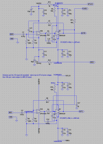
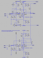
Here is the up to date spice schematic, with correct board component IDs, but not the same IO names.
The TI SPICE macro model for the LMH6321 was modified to include some additional IOs and functions that are in the device description but are not supported in the original version from TI.
In case anyone asks I am unwilling to share a non TI supported model.
The TI SPICE macro model for the LMH6321 was modified to include some additional IOs and functions that are in the device description but are not supported in the original version from TI.
In case anyone asks I am unwilling to share a non TI supported model.
Attachments
Last edited:
Nice amplifier and results!
Why you decided to use LMH6321 rather than much more popular LME49600 or BUF634A? Any particular advantages?
R5 & R6 looks unusually high to me. I used to see 100Ω or even no resistor at all at that position in various datasheets or Walt Jung book.
Why you decided to use LMH6321 rather than much more popular LME49600 or BUF634A? Any particular advantages?
R5 & R6 looks unusually high to me. I used to see 100Ω or even no resistor at all at that position in various datasheets or Walt Jung book.
The extrapolated distortion characteristics for the 6321 seemed to be better than the BUF634A under equivalent conditions when I calculated the net results when in a composite with the OPA1656. There were other, secondary concerns, but that was it.
I did not consider the LME49600.
The 10k value is indeed higher than is often used, a 510 ohm value seems more typical, but it corresponds to the app. note value specified by TI and is intended to protect the buffer under essentially shorted output conditions by limiting the total "inrush" current. Ti specifies two different values in their notes, the 10k value being a justified correction for the lower value. The OPA1656 is near rail to rail output and under circumstances where the loop can lose feedback control it is easy to exceed the max current without this higher value resistor and compromise the reliability of the device.
The 10k does present a problem as the additional pole introduced by the resistor and the (if I remember correctly) 3pF input cap of the 6321 plus the parasitic board cap (estimated to be c.2pF) can cause stability issues close to the unity gain bandwidth of the opamp- about 20MHz or so. The 1nF lead compensating cap takes care of this issue.
") .
. - Home
- Amplifiers
- Headphone Systems
- Low cost, high performance headphone amp using OPA1656 and LMH6321