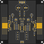
It's bigger than the prototype board. The 100uF caps should also be more proximate to the buffers. I can't tell anything about the thermal pours for the buffers, but generally vias are placed directly under the pad to the bottom side board as the thermal efficiency falls off as you move away from the pad, especially with normal thickness copper, and having both sides acting as efficiently as possible as heat sinks is essential. Heat sink areas on each side bigger than about 1.5 sq ins. are essentially pointless with 2oz copper. The 100uF caps are long life, high temperature varieties in order to maximize their lifetime in close proximity to the buffers.
I'm not a fan of opamp rolling. You can do it you want, but unless you want to use a decompensated part and add the circuitry to make the loop think that it's operating at a higher noise gain in an appropriate region to stabilize the loop, I wouldn't recommend it. Most other opamps will exhibit degraded specs in this application, and many will be unstable or exhibit other pathologies.
In any case, I don't intend to critique this further.
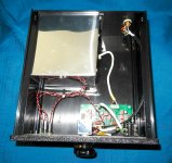
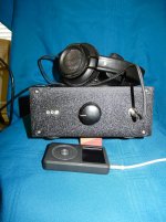
Completed Wyn Palmer headphone amp
It really does sound fantastic! Extremely detailed, in fact - so much so I'd like the ability to roll off some highs for some recordings, but it is really dynamic, clean and quiet.
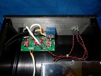
My original layout induced some PS noise, so I rearranged the board, made a cover for the PS enclosure I made, and re-routed all signal cables and the power wires. It is now so quiet it has to be turned up full blast to catch even a hint of electrons buzzing around. If I had played music at that level I'd be deaf.
In fact, it is so powerful I can't safely use the line jack on my Fiio hi-resolution player - have to use the volume-controlled headphone output jack.
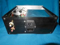
I went retro-look; it is rather anachronistic to listen to 2-channel stereo in today's world, even more so to listen at home through headphones while, heaven forbid, reading! Went with wrinkle black on the front panel to match the old ham radio knob from my father's gear. Two green leds are power indicators - one for each rail, and wired for very low current draw. Yellow fault indicator is just to the right. Everything would have fit in a 1 - 1.5" shallower cabinet, but this is what I had on hand.
Well done on the design and performance, Wyn. I am very glad you took the bait and designed this. And Sean - you are getting really skilled at laying out a bunch of really tiny components for great performance.
It really does sound fantastic! Extremely detailed, in fact - so much so I'd like the ability to roll off some highs for some recordings, but it is really dynamic, clean and quiet.
My original layout induced some PS noise, so I rearranged the board, made a cover for the PS enclosure I made, and re-routed all signal cables and the power wires. It is now so quiet it has to be turned up full blast to catch even a hint of electrons buzzing around. If I had played music at that level I'd be deaf.
In fact, it is so powerful I can't safely use the line jack on my Fiio hi-resolution player - have to use the volume-controlled headphone output jack.
I went retro-look; it is rather anachronistic to listen to 2-channel stereo in today's world, even more so to listen at home through headphones while, heaven forbid, reading! Went with wrinkle black on the front panel to match the old ham radio knob from my father's gear. Two green leds are power indicators - one for each rail, and wired for very low current draw. Yellow fault indicator is just to the right. Everything would have fit in a 1 - 1.5" shallower cabinet, but this is what I had on hand.
Well done on the design and performance, Wyn. I am very glad you took the bait and designed this. And Sean - you are getting really skilled at laying out a bunch of really tiny components for great performance.
Attachments
Thank you for your input ")
Yup. I have a few different template sizes that I work from. Makes screwing them down on my bench easier.
Trace length is around 4.7mm from the 100uF buffer caps to the 100nF caps. I'll see if I can get em closer.
There are vias under the pad but for some reason they didn't render in the image.
If this goes to fab it'll likely be 1oz.
These will be Rubycon YXM caps (or similar).
I'm not sure how to interpret this - if I have offended you somehow I apologise . I am not an engineer, just an amateur and I do this hobby for the fun of it.
It's bigger than the prototype board.
Yup. I have a few different template sizes that I work from. Makes screwing them down on my bench easier.
The 100uF caps should also be more proximate to the buffers.
Trace length is around 4.7mm from the 100uF buffer caps to the 100nF caps. I'll see if I can get em closer.
but generally vias are placed directly under the pad to the bottom side board
There are vias under the pad but for some reason they didn't render in the image.
Heat sink areas on each side bigger than about 1.5 sq ins. are essentially pointless with 2oz copper
If this goes to fab it'll likely be 1oz.
The 100uF caps are long life, high temperature varieties
These will be Rubycon YXM caps (or similar).
In any case, I don't intend to critique this further.
I'm not sure how to interpret this - if I have offended you somehow I apologise
. I am not an engineer, just an amateur and I do this hobby for the fun of it.Not a matter of offense, it just isn't particularly convenient at this time.Thank you for your input
Yup. I have a few different template sizes that I work from. Makes screwing them down on my bench easier.
Trace length is around 4.7mm from the 100uF buffer caps to the 100nF caps. I'll see if I can get em closer.
There are vias under the pad but for some reason they didn't render in the image.
If this goes to fab it'll likely be 1oz.
These will be Rubycon YXM caps (or similar).
I'm not sure how to interpret this - if I have offended you somehow I apologise
However, having said that, the caps you have chosen are fine. I don't know why you wish to change the BOM, but it's your choice. Also, with lower weight copper, making the pours larger has even less value. Stick with 1oz, <=1.5 sq in copper per side.
Last edited:
Thank you for that.
I didn't see a BOM in the thread. Did I miss something?I don't know why you wish to change the BOM
I love that knob!
Thanks! It looks even cooler in real life and feels like it was meant to be used a lot - typical for ham gear.
By the way, not sure if you were aware that the project didn't require you to come up with a board design - it has already been done and is excellent. I believe a second version is in the works, as well.
I will order a second run if the demand is there. Frankly I was surprised at the popularity of the first run. The changes are essentially cosmetic as no functional/performance problems have been reported so far.
The first run was a dual design with a phono warp/elliptic filter intended for add-on to a phono preamp. No further requests have been made for that so the second headphone run will be either stand alone or an add on to the ultra high performance phono/ line design v2.0.
The first run was a dual design with a phono warp/elliptic filter intended for add-on to a phono preamp. No further requests have been made for that so the second headphone run will be either stand alone or an add on to the ultra high performance phono/ line design v2.0.
I did indeed see that the board is availableBy the way, not sure if you were aware that the project didn't require you to come up with a board design
. I just really enjoy the process - heapdhones on, some good tunes, and few hours creating a layout is thoroughly satisfying.Very nice project.
Reading through, I stopped at this:
I get the point about the difficult package of the opa1622 but why not simply going with just 2 opa1656 per side then ? Thermal concerns ? Stability in capacitive loads ? This is really not a criticism, the results speak for themselves, I'm just curious.
Reading through, I stopped at this:
Yes, I contemplated using OPA1622s- essentially two duals per channel- three amps in parallel with the fourth as an input stage.
I get the point about the difficult package of the opa1622 but why not simply going with just 2 opa1656 per side then ? Thermal concerns ? Stability in capacitive loads ? This is really not a criticism, the results speak for themselves, I'm just curious.
The OPA1622, like the LMH6321, comes with a thermal pad attached to the substrate (I believe). This is intended to maximize heat dissipation using a suitable thermal pour on the board. As a result it can handle a wide range of headphone impedances and provide acceptable output power. It also has defined short circuit protection and other headphone specific features. The OPA1656 lacks these capabilities, or the features are insufficiently specified- it not being specifically intended for headphone driving use so why bother?
The thermal TC on the OPA1656 is also extremely short as a result of the package options available, and if you operate it at elevated temperatures, as would be the case if it were directly driving a low impedance headphone, the noise performance obviously will degrade, as will the maximum output current and voltage vs. temperature, making it potentially less suitable in a wide range of supply/headphone impedance environments. I cannot be more specific as to what those boundaries are as I did not consider the details in depth.
Those were the principal reasons.
When I proposed the idea of the headphone amp to Wyn, one of the limiting parameters for the design and choice of components he considered was the need to drive my 30 Ohm headphones. I recall Wyn eliminating some devices early on as a result.
I used my new build for over an hour with the cover off to check operating temps; the devices barely got warm. Another 1.5 hours with the cover on - flawless functioning. I can't imagine a situation where the thermal fault indicator would be triggered at tolerable listening levels.
The only observation, which may be particular to the use of low impedance headphones I'm using (WAG on my part), is that it would be nice to be able to roll off high frequencies with some recordings.
I checked the frequency response into a variety of loads. It remains flat from a few Hz until you get to the multi MHz region, even with demanding, complex, loads.When I proposed the idea of the headphone amp to Wyn, one of the limiting parameters for the design and choice of components he considered was the need to drive my 30 Ohm headphones. I recall Wyn eliminating some devices early on as a result.
I used my new build for over an hour with the cover off to check operating temps; the devices barely got warm. Another 1.5 hours with the cover on - flawless functioning. I can't imagine a situation where the thermal fault indicator would be triggered at tolerable listening levels.
The only observation, which may be particular to the use of low impedance headphones I'm using (WAG on my part), is that it would be nice to be able to roll off high frequencies with some recordings.
Reducing the bandwidth means reducing it prior to the amp. A cap across the FB resistor will not help as the closed loop gain is only 6dB.
You could add a series R, say 10k and switch in a shunt cap external to the board input. Under these circumstances an 820pF cap would give you a -3dB point at 20kHz.
Or, you could use a series pot at the input, together with a fixed minimum R and a fixed cap and adjust it to add a low pass.
Like a Boss: The Philips Fidelio X2 Page 2 | Stereophile.com
I believe that you have the X2.
"everything is accentuated on the X2" is a quote. The 1k-10k region is pretty spikey with 12dB deviations. Perhaps what you see is what you get...
I have an HD800S and it has similar elevated treble and deviation.
HD800S | DIY-Audio-Heaven
It sounds quite nice, but with, in some ways, excessive detail.
- Home
- Amplifiers
- Headphone Systems
- Low cost, high performance headphone amp using OPA1656 and LMH6321