under
Schiit Audio: Audio Products Designed and Built in California
I read this:
Choose Magni 3+ for the ultimate expression of an affordable all-discrete current-feedback headphone amp. It’s now seriously like a mini speaker amp, right down to the driver stage and Vbe multiplier. Magni 3+ is in our traditional silver and gray chassis.
but in post #130 under
Review and Measurements of Topping A30 and Schiit Magni 3 Headphone Amps | Page 7 | Audio Science Review (ASR) Forum
and
Schiit Magni 3 abgefackelt - Verstarker, Lautsprecher, Zubehor - Analogue Audio Association
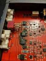
so as in the attachment (first both images) you will find versions with destroyed output stages.
A headphone friend I know well wanted to hear my opinion on this device because he is playing with the idea of getting this device.
But after checking the web I found the above mentioned (I was shocked), so that I strongly advise against buying it.
Nevertheless I want to know the reason for that or at least the schematic, which isn't online for download.
Schiit Audio: Audio Products Designed and Built in California
I read this:
Choose Magni 3+ for the ultimate expression of an affordable all-discrete current-feedback headphone amp. It’s now seriously like a mini speaker amp, right down to the driver stage and Vbe multiplier. Magni 3+ is in our traditional silver and gray chassis.
but in post #130 under
Review and Measurements of Topping A30 and Schiit Magni 3 Headphone Amps | Page 7 | Audio Science Review (ASR) Forum
and
Schiit Magni 3 abgefackelt - Verstarker, Lautsprecher, Zubehor - Analogue Audio Association
so as in the attachment (first both images) you will find versions with destroyed output stages.
A headphone friend I know well wanted to hear my opinion on this device because he is playing with the idea of getting this device.
But after checking the web I found the above mentioned (I was shocked), so that I strongly advise against buying it.
Nevertheless I want to know the reason for that or at least the schematic, which isn't online for download.
Attachments
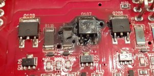
Personal opinion ?--- output devices made for color TV --high speed switching ( not audio ) --personal conclusion ?--- HF oscillation under conditions appropriate to Audio use .
Nice neat devices appropriate in the correct design hardware --TV,s ---design issue.
I am sure the name will draw criticism of my conclusion BUT rather than criticize TELL the poster why its happening if its not what I think it is.
Nice neat devices appropriate in the correct design hardware --TV,s ---design issue.
I am sure the name will draw criticism of my conclusion BUT rather than criticize TELL the poster why its happening if its not what I think it is.
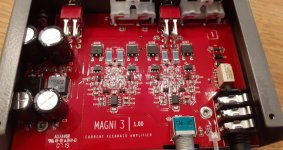
same device, but wrong headline:
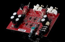
What's in the box?
more url's:
Schiit Magni 3+ Headphone Amp Teardown | Audio Science Review (ASR) Forum
Schiit Magni 3+ vs Magni Heresy Amplifiers Review
What's in the box?
more url's:
Schiit Magni 3+ Headphone Amp Teardown | Audio Science Review (ASR) Forum
Schiit Magni 3+ vs Magni Heresy Amplifiers Review
Last edited:
If one npn is toast plus the pnp on the other channel, this may suggest that L and R had been shorted together - this can happen momentarily in headphone jacks when plugging/unplugging. I would test for continuity between L and R just in case, and if found, inspect the headphone jack solder joints first and follow the PCB traces back if need be.
It would appear, then, that the circuit's short circuit proofing leaves something to be desired (well... presumably there isn't any). It should be obvious that a $99 commercial product won't be overbuilt in the way DIY designs often are, and I guess they didn't want to compromise power output either.
The point where it gets concerning to me is when the amplifier even gets hot yet still isn't blowing a fuse. That definitely shouldn't be happening.
I agree with sgrossklass. Those pictures likely show a catastrophic sudden failure. The only protection against a short appears to be the 4.7r emitter resistors. Combined with transistors running hot and thus a degraded SOA, a short could easily kills the output transistors.
- Status
- This old topic is closed. If you want to reopen this topic, contact a moderator using the "Report Post" button.
- Home
- Amplifiers
- Headphone Systems
- Schiit Magni 3+ Headphone Amp - what reason for burned Push-Pull Output Buffer Stage?