Hello,
I made several headphone amp with quite high expectation. I have one I like, it is a single ended class A tube one, but it is a monster.
Solid state ones, I did built a few and also listened a few very famous and with good reputation.
Most solid states I just did not like. Like beta22 is extremely well detailed, but also makes me tired after 10-20min. I also tested tube amp which was not my taste, easy listening, but lacks details somewhat.
I was surprised to see the Sennheiser's HDV-820 use TPA6120's. In balanced config. I did built a normal 'inbalanced' one before and I kind of liked it, but it was very depending on the PSU, (I found most headphone amp does.), tried with batteries also, the best PSU was some scrapped Agilent 6627A, which is a monster too, but I just could not make a better PSU. That time I did not hear the "superreg's".
Now I checked the HDV-820 with my source and my headphone and I have to say I was surprised and liked it. I found it very detailing while it is still not made me tired. That is the balance what my normal, 2A3 PSE amp does and fills the room and this is eaxctly what I was looking for in headphone amps + some portability, at least less than 10kg.
So now, I want to bring the best out of the TPA6120A2, with superreg and with the old monster HP6627A. I've just ordered some PCB's, it is coming.
Do you guys know more of this chip? What voltage level is the best to use (for 300 Ohm headphones)? What feedback resistor? What else, to get the best out of it?
Thanks,
JG
Attachments
I bought a couple of these Chinese boards with Pavouk's layout to try, but still haven't gotten around to connecting them (sidetracked by O2 and ACP+ preamp). Plan to run one on +/-12V (maybe using Murata SR7812) and one on +/-15V using cheap TPS7A type vregs.
If you poke around there are a couple of versions using TPA6120 plus an input buffer....
But yes, at least you are on the right track about the PS being critical, and generally very expensive (10:1) relative to the actual audio circuit.
If you poke around there are a couple of versions using TPA6120 plus an input buffer....
But yes, at least you are on the right track about the PS being critical, and generally very expensive (10:1) relative to the actual audio circuit.
Attachments
Last edited:
Hello, I agree mostly, but not fully. I did tested expensive power supplies, like the beta22's "original" psu, also some fancy new super low noise regulator IC, but without success. I found the cheap old LM317/337 brings a very decent result, also a zener shunt regulator better for low power circuits.
I've also played with transformers and found it is important to under utilze the core, I mean B is about 0.8 * Bmax. Sometime I found big transformer is the best choice, but than I found, small, but under utilized (not sure what is B in English, basically more far from saturation on peaks) transformer can be even better.
Anyway, another thing, I never tried with LiPo batteries, now I will. Straight 2+2 cells without regulation. I did used others with SLA batteries, it was not bad, but the big HP lab psu was still better.
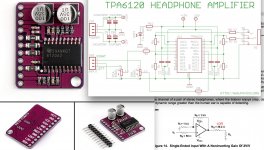
Read the Datasheets of TPA6120A2 and THS6012. They are high-speed current feedback amplifiers and the feedback resistance value plays a role in setting their bandwidth (incorrect values can cause peaking and other trouble). If you check the datasheets, the reasonable range of feedback resistor values starts somewhere around 750 or 820 Ohms with 1kOhm being the general recommendation from application examples if I remember correctly. The THS6012 datasheet is more detailed in some aspects, although the TPA6120A2 datasheet has at least one graph regarding this as well. I also don't know if the devices are 100% identical or if they have any slight differences in internal compensation.
I also might add that what Andersonix described as an Input buffer might really be the VFA part of a VFA-CFA Composite amplifier. This is probably also the way to get the most out of this chip, BUT I would strongly suggest you only follow this approach if you have access to a reasonably fast scope so you can check for oscillation. Look at datasheets, evaluation boards as well as other commercial or noncommercial implementations and strive for a compact but clean layout, no matter what approach you end up choosing.
I also might add that what Andersonix described as an Input buffer might really be the VFA part of a VFA-CFA Composite amplifier. This is probably also the way to get the most out of this chip, BUT I would strongly suggest you only follow this approach if you have access to a reasonably fast scope so you can check for oscillation. Look at datasheets, evaluation boards as well as other commercial or noncommercial implementations and strive for a compact but clean layout, no matter what approach you end up choosing.
Last edited:
I also might add that what Andersonix described as an Input buffer might really be the VFA part of a VFA-CFA Composite amplifier. This is probably also the way to get the most out of this chip, BUT I would strongly suggest you only follow this approach if you have access to a reasonably fast scope so you can check for oscillation.
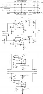
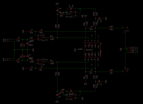
I attached the two schematics using input buffers that I've seen here at Diyaudio.
Also attached a photo of the Rubert Neve RNHP which appears to use an input buffer, along with output caps.
Attachments
I made stereo head amp in se mode with this chip and have a problem, it has 1K5 feedback resistors and 10k pot on the input, no buffer or servo. On one channel I get 250mV offset when pot is at zero and goes to 2V at input pot to max, I know the chip have high input current and offset problems but this is odd. It happens only on one part of the chip, another half have about 10x less offset. The power supply is properly decoupled like as datasheet recommends.. Any ideas?
Hello,
You can take a look at my composite TPA6120A2 headphone amplifier.
High performance OPA1602 + TPA6120A2 Composite Headphone Amplifier
You can take a look at my composite TPA6120A2 headphone amplifier.
High performance OPA1602 + TPA6120A2 Composite Headphone Amplifier
I attached the two schematics using input buffers that I've seen here at Diyaudio.
I recognise one of those
 ! That amp is in daily use. Composite TPA6120 with servo HPA
Be sure to pay attention to the layout guidelines in the data sheet, especially the part about not having ground pour under the input pins.
Your projects are works of art, Donthertzme!
Thank you kindly

I have a board for the THS6012 that's been staring at me for a few weeks now.
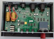
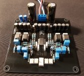
I am listening to a balanced version for a few weeks now and I can say I'm impressed. The source is a cheap Chinese DAC, which is not bad, but I think my AD1865 based DAC is still better. Anyway, after some experiment on the bench, I built it on a piece of wood and listening for it. I think it is either the "superreg" PSUs, which are really good (too bad that I ignored them for years) or the balanced config.
It has a natural, wide soundstage, no problem with top and bottom and the main thing is, while it is detailed, does not make me tired. It is for sure in the direction to a triode SE OTL I built on my firend's design. It is not the same at all, can not really tell which is better, but I feel this is my first solid state headphone amp what I like.
It has a natural, wide soundstage, no problem with top and bottom and the main thing is, while it is detailed, does not make me tired. It is for sure in the direction to a triode SE OTL I built on my firend's design. It is not the same at all, can not really tell which is better, but I feel this is my first solid state headphone amp what I like.
Attachments
around 10uA, but that is not a problem in this circuit. It is good to keep in mind because I have a DAC where the signal is coupled out with cap. I do not intent to mix. So, I will use the tube output DAC with tube amp.
This one is made to be portable. I mean, room to room, not on the street
This one is made to be portable. I mean, room to room, not on the street
Hello,
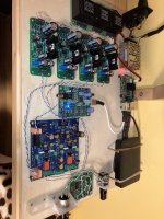
I have tried to build a DAC+headphone amp from a Chinese DAC pcb, 4 superreg PSU and a balanced TPA6120 amp. The DAC is bad. But, the headphone amp paired with the superregs became a great success. I really enjoy it. Detailing, but not harsh. Pairs well with my sennheisers.
I'm desigining a more compact version, I include the status here, if you guys have time to review it and has comments, I appreciate that.
Thanks,
JG

- Home
- Amplifiers
- Headphone Systems
- How to get the best out from a (or 2) TPA6120A2