Because of the corona mess (I can't go home) and high import costs for "exotic"
components ordered from out of the country , I made a small and simple test
HPamp with the easy to get and very cheap NJM2068 and NE5532.
I had to test the power supply (Elvee's DeNoiser), and protection circuits I had
build with something other than LED's.
Last interesting HPamp design I saw , was with the now discontinued (boo T.I)
LM49600 like in its application information . It's a simplified version of tomchr
(neurochrome)'s HP1 which he isn't sharing . Another is an HPamp with
OPA1622, but this is ridiculously small ( double boo for T.I).
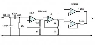
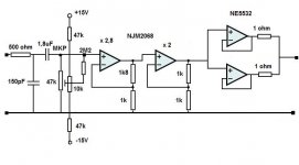
My objective is to have an HP amp that can take my 300 ohm HP's with the tiny
signal from my computer and Mp3 player. They can't handle 300 ohms.
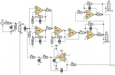
So I made a simpel (boring) one :
After the 1,8uF I measured 7mVdc offset ! (with or without input signal . After the
cap I expected 0mV) . I guess this is the 2068's 150nA input bias current going into
the 47k ? It gets amplified 5,6 times and combined with the 2068 and 5532's offset
to show 37mV at the output. Now I know why nwavguy's O2 has the cap behind the 2068.
Makes a case to lower the 47k to 10k or less , but then the input cap should be
bigger.
Here are my questions:
Am I right that this is the 150nA bias current that creates this 7mV DC offset?
Is there an other easy solution to get that offset down? (no servo).
I'm now using it with an 32 ohm HP :
Is 37mV dc on output dangerous for a small on the ear HP ?
Can I use the NE5532 like used here ( on 2 x 14.6V) with a 32 ohm HP without
damaging it?
Both 2068 and 5532 get hand warm .
The 5532 comsumes about 8mA x 29 V= around 232mW , the LM317/337 deliver 18mA with 7V over them = 126 mW , yet the LM's feel warmer . Weird.
The amp sounds good , like a fuller sound compared to the computer output. But that could be subjectieve.
components ordered from out of the country , I made a small and simple test
HPamp with the easy to get and very cheap NJM2068 and NE5532.
I had to test the power supply (Elvee's DeNoiser), and protection circuits I had
build with something other than LED's.
Last interesting HPamp design I saw , was with the now discontinued (boo T.I)
LM49600 like in its application information . It's a simplified version of tomchr
(neurochrome)'s HP1 which he isn't sharing . Another is an HPamp with
OPA1622, but this is ridiculously small ( double boo for T.I).
My objective is to have an HP amp that can take my 300 ohm HP's with the tiny
signal from my computer and Mp3 player. They can't handle 300 ohms.
So I made a simpel (boring) one :
After the 1,8uF I measured 7mVdc offset ! (with or without input signal . After the
cap I expected 0mV) . I guess this is the 2068's 150nA input bias current going into
the 47k ? It gets amplified 5,6 times and combined with the 2068 and 5532's offset
to show 37mV at the output. Now I know why nwavguy's O2 has the cap behind the 2068.
Makes a case to lower the 47k to 10k or less , but then the input cap should be
bigger.
Here are my questions:
Am I right that this is the 150nA bias current that creates this 7mV DC offset?
Is there an other easy solution to get that offset down? (no servo).
I'm now using it with an 32 ohm HP :
Is 37mV dc on output dangerous for a small on the ear HP ?
Can I use the NE5532 like used here ( on 2 x 14.6V) with a 32 ohm HP without
damaging it?
Both 2068 and 5532 get hand warm .
The 5532 comsumes about 8mA x 29 V= around 232mW , the LM317/337 deliver 18mA with 7V over them = 126 mW , yet the LM's feel warmer . Weird.
The amp sounds good , like a fuller sound compared to the computer output. But that could be subjectieve.
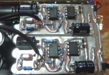
Attachments
https://www.ti.com/lit/an/sloa059/sloa059.pdf
This one is a good read regarding what input voltage offset is and what causes it.
What about simply putting a cap at the output?
This one is a good read regarding what input voltage offset is and what causes it.
What about simply putting a cap at the output?
Here are my questions:
Am I right that this is the 150nA bias current that creates this 7mV DC offset?
47k x 150nA = 7mV, so absolutely it does.
Balancing the DC impedances seen by both inputs - however this would increase the Johnson noise significantly from the feedback network. A large capacitor and small resistor would do the job between two of the stages, say 47uF and 1k, which reduces the offset to 1k x 150nA = 0.15mVIs there an other easy solution to get that offset down? (no servo).
Changing to a JFET or MOSFET input opamp would finesse the problem of course as the bias currents are orders of magnitude smaller.
power = 43µW, so not at all. However it might increase distortion by biasing the diaphragm off-centre in the transducer.I'm now using it with an 32 ohm HP :
Is 37mV dc on output dangerous for a small on the ear HP ?
Opamps are universally short-circuit protected, I can't think on one that isn't.Can I use the NE5532 like used here ( on 2 x 14.6V) with a 32 ohm HP without
damaging it?
However the 5532 will have increased distortion as the load falls below 500 ohms with large signals. For small signals its probably doing just fine.
Heat dissipation is mainly through the legs of the chip to the groundplane of the PCB, so can vary depending on leadframe geometry in the chip and pcb layout.Both 2068 and 5532 get hand warm .
The 5532 comsumes about 8mA x 29 V= around 232mW , the LM317/337 deliver 18mA with 7V over them = 126 mW , yet the LM's feel warmer . Weird.
All listening tests are subjective unless double blind or ABX with many many repetitions to pull out the statistical pattern.
The amp sounds good , like a fuller sound compared to the computer output. But that could be subjectieve.
Thanks Mark Tillotson for confiming that it is the 150nA input bias current.
Of course a jfet or mosfet opamp would solve it.
Putting a smaller cap between 2068 and 5532 is the O2 solution and beter than a electrolytic cap on the output. 5532's offset is not a big problem. A 2,2uF MKT is not that big to fit between the 2 on the PCB.
Of course a jfet or mosfet opamp would solve it.
Putting a smaller cap between 2068 and 5532 is the O2 solution and beter than a electrolytic cap on the output. 5532's offset is not a big problem. A 2,2uF MKT is not that big to fit between the 2 on the PCB.
Would you consider configuring into a differential input? This will eliminate most of the DC bias.
What's your source?
Do you need a volume pot?
It's a test amp , making a differential input would be difficult on the made PCB.
Source is computer audio output and MP3 player .
Don't need volume pot , because the sources have it even my CD player .
Why do you need the input coupling capacitor?
Without it, the 47k could instead be much smaller, as long as the source could drive it.
If you still want a high pass, the series cap can go before the 5532.
The MP3 has a couple of mV dc on it's output.
Yes the cap before the 5532 like the O2 seems best.
Last edited:
I just had a look at the 5532 input bias current , and it's 200nA typical. So a 2,2uF and 10k or so would create the same problem but less because there is no amplification . Because of the npn input it would have a negative voltage over the 10k ? , around 2mV. Still better than 37 mV now.
It's a test amp , making a differential input would be difficult on the made PCB.
Source is computer audio output and MP3 player .
Don't need volume pot , because the sources have it even my CD player .
Then input cap also don't need. PC and MP3 player already bias at 0 volt.
I'm actually doing this currently. 2 op amp and less than 20 resistors for a stereo.
Attachments
^ Like I said in post 10 : Mp3 player has a couple of mV on its output.
A cap on the input protects the source too . I had one Jfet opamp broken and had -11V on it's input . Gate of the fet broken ? Not risking my old computer with a dc input.
Instead of differential input or like my non-inverting opamps , I could have made 2 inverting , with the non-inverting input with a resistor to the ground to compensate the bias input current , but with more noise.
I had a look at the 5532 Opamplifier of Douglas Self (Elektor 10-2010) . There the 5532 are also (at the beginstage ) non-inverting amps . No mention that the 200nA over 47k will cause > -9mV ... Amplified by 12-13 (22,7dB) , that's -100mV after the amplification stage before going to the paralelled 5532 output stage. No caps after the input stage. So the servo (OP177) , has to compensate for this ? Nothing in the text says something about this.
I based my simpel test HP amp a bit on this and the O2 .
Attachments

^ Where I live as an expat , there is low VAT but import taxes are large. International payment is a problem too and expensive, delivery costs are a wild card. The local suppliers don't have the latest new opamps.
For a test amp , NJM2068 was easy and cheap to get. I did not anticipate that the input bias current would make such a big dc voltage . The only low noise Jfet I can get is LF353 . Not really a good one. ( never mind the TL072).
The only foreign company I can use , but with a financial risk is RS.
Normally I would go to europe and buy there , but with the chinese corona virus , it's not posible.
I love CMOS , in logic (4000 & HC's) ,the revolutionairy TLC271 at the end of the eighties , fantastic ! But even now with the new materials , I'm not in favor for CMOS audio amps. RS doesn't even have the CMOS OPA1656 . Besides in their application notes pg 14 : they employ BUF634 with the 1656 for low impedance HP's....instead of 2 (or more) in parallel. And the 1656 is only in smd.
Changing the 2068 would be the best solution . Cheap test opamps that RS does have are: Jfet OPA1641 but only in smd . LME49720 (5nA input current) but also only in smd. They don't have the LM4562. OPA1602 with 20nA input current in smd.
I don't like an opamp on 2 x 15V as an smd . PDIL is cooler. In smd, maybe with some Aluminium cooler on it but not much room for it. Not many of the latest opamps are in PDIL . I said it before , while some T.I designers think it's OK for an opamp to heat up above 100 C or even 150 C , I think it is not ok.
So the choice for the easy 2068 and 5532 was obvious.
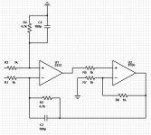
A quick and easy way to lower the output offset because of "input bias current challenged opamps" ( AD797 , NE5532, NJM2068.....) , is the poor man's servo method.
What does an opamp servo do ? It injects a dc voltage to compensate for the dc in the output whether that is because of dc coupling , high input bias current over a resistor , or the input offset of the opamp itself.
Do the same but not with an opamp but with a trimpot. It works , I can get the output to less than 100uV.
Of course adjust when opamp is at its working temperature to compensate for temp drift.
And it doesn't work for dc coupled inputs where the dc is not as constant as the input bias current.
With so low voltages and current through 1 to 10 Mohm from the trimpot to the input , I doubt it will make noise worse. Servo opamps do it this way , so why not a trimpot .
Even low bias current bipo opamps like LM4562 have 10nA : 10nA over 47k input R = 470uV x amplification , here 5,6 = 2,63mV on its output + or - their voltage input voltage offset.
Also it is a method of injecting DC in the ouput for testing DC detectors & protectors.
Not sure why no one has suggested this , this is nothing new .
Attachments
Last edited:
- Status
- This old topic is closed. If you want to reopen this topic, contact a moderator using the "Report Post" button.
- Home
- Amplifiers
- Headphone Systems
- Simple HP test amp questions