Yes the LM4562 has got impressive figures but those types didn't impress D.Self .
I see what the rejection values are for it but that wouldn't stop me fitting PSU suppression components to it, I am a "belts & braces" man , it comes down to -- does it sound good to ME -- and that is the ultimate test not a THD meter reading of over 100db.
I see what the rejection values are for it but that wouldn't stop me fitting PSU suppression components to it, I am a "belts & braces" man , it comes down to -- does it sound good to ME -- and that is the ultimate test not a THD meter reading of over 100db.
Thanks duncan2 for your post. I fully agree with you.
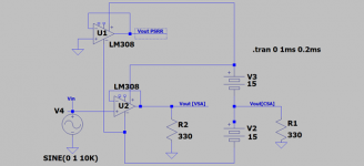
The application understudy is a test method for PSRR. The attached schematic shows:
1. LM308 [U2] is the application understudy. It generate two out of phase output signals; namely Vout [VSA] and Vout [CSA].
2. The signal Vout [CSA] is a "disturbance" on both rails of +/-15 V PSU. It has magnitude and phase.
3. This disturbance causes a change in [U2's] Vout [VSA]; per the definition of PSRR; but I can't measure it at this location.
4. This same disturbance is seperately imposed on the rails of an independent LM308 [U1]. It is idle. The LTSpice model shows an emerging output voltage [Vout PSRR]. It has amplitude and phase. This method is fully applicable to a dual [or true twin] OpAmp like NE5532.
5. 20 Log {Vout [VSA]} divided by {Vout [PSRR]} is a calculated PSRR at 10 KHz. The resultant value is 60 dB.
6. The two signals in point 5 are in phase; but with a phase shift per LTSPice.
7. But suppose the two signals in point 6 are in-phase. This creates or is an internally-induced positive feedback. A possible cause of oscillation if excessive; but maybe beneficial in its abscence if low or moderate.
NB.
Vout [VSA] and Vout [CSA] are correlated and out of phase. They are a balanced pair of outputs which are suitable to drive bridge amps.
Best
Anton
Attachments
A Simply-Balanced Stereo Headphone Amp
The attached image shows the prototype's schematic for one channel and its Spice model; which runs smoothly.
Please note the following:
1. This HA has independent +/- 12 to 15 V PSUs. Their regulation in my application is not needed. This PSUs' independence favourably affects channel separation.
2. The stereo phones are independent of each other. They do not share a common/ground. Please recall I had cut the plug on my Grado Labs [SR80] and separated their leads. This favourably affects one's preferred perception of H2; do you like +H2 or -H2? Reversing the leads of each phone will give the opportunity to sample H2.
3. The stereo proto HA uses two NE5532s. One per channel. Sounds superb.
4. I have another application for the idle twin OpAmp in each channel .
5. Spice model says one can increase the value of the balancing resistors [330 Ohms shown] to 10 K each. More output power goes to the phone.
6. The OpAmp inverts phase. Gives one the opportunity to balance volume level between L and R phones. This is done by slight changes in the unity gain of one [say L ch] relative to that of [R ch].
7. The OpAmps can also be operated non-inverting without problem.
Best
Anton
Attachments
The OpAmp power rails did not have decoupling caps [e.g. 0.1uF] in my last posted schematic. They suppress high frequency oscillations [>100 KHz.]
The attached schematic is an LTSpice model which shows the effect of one decoupling cap [0.1uF] at Vo [current source]. The sampling frequency is 10KHz instead of 1 KHz. The resultant behaviour is a low pass filter for/at the power rails
1. Vout [current source] is reduced in amplitude relative to that at Vo [voltage source].
2. Vo [current source] is phase-shifted relative to Vo [voltage source].
One may get away with lower-valued decouple caps.
I used the learnings todate on a 75 W/ch [8 Ohm] discrete power amp module by Radio Shack [STA-2000D]; vintage 1979. I have its schematic. Here's the experiment and subjective outcome.
1. It retained the decouple caps [0.11 uF] at its power rails [+/-45 V] to ground. Without them, the amp oscillates. May remind of the residual oscillation at the output of Class D; high enough to be irrelevant.
2. Cut the PCB around electrolytic caps [100 uF] connecting Vo[current source] to ground. They'll bypass power to ground!.
3. The amp is stable, no trace of oscilation, and it idles a +/- 70 mA.
An 8 loudspeaker [Karlson] was connected as shown in the attached schematic. It sounded great, loud and clear.
The take-away messages are:
1. Adaptable to low power discrete OpAmps.
2. Scalable for high power integrated amps e.g. LM3886.
3. Audio signals on the power rails constitute a possible added global feedback [- or +] to the stages preceding the power output stage. Granted their circuits ingest this feedback.
Best
Anton
Attachments
Simple Operational-Headphone Amp
The attached schematic is for the subject discrete prototype.
Notables are:
1. Fully satisfactory sound. Does not hum, buzz or whistle.
2. The elements enclosed with rectangles are essential for stability against oscillation.
3. Avoided using constant current sources [CCS], and active loads [AL]. The power output [Vout-] is fully available as additional possible global feedback to all of the amp.
4. Disconnect the 47 pF cap to run its Spice model. Its harmonics look great.
It can be upgraded with the traditional [CCS] for the input diff amp, and with an [AL] for the last voltage amp instead of its 4.7K. But it works fine without these established enhancements.
Best
Anton
Attachments
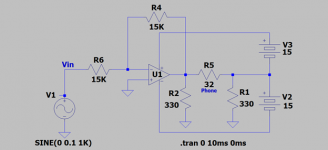
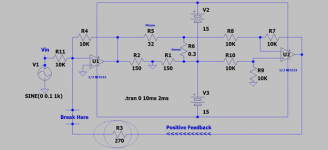
Adding Positive Fedback to a Balanced Headphone Amp
The attached schematic is for the subject prototype. Positive feedback increases gain [and noise!] and boosts damping factor. Too much of this good feedback will cause the amp to oscillate.
Please note the following:
1. I had prototyped the circuit of U1 only and posted it earlier. Its is a great-sounding performer. It does not hum, buzz or whistle. Note the absence of PSU decoupling capacitors and a Zobel across the load
2. Note the new sense resistor [R6 = 0.3 Ohm]. A voltage drop emerges across it from the current flowing through the load [32 Ohm] in series with it.
3. This sensed voltage feeds a unity gain differential amp [U2]. The voltage output of [U2] is in phase with [Vin]. It is summed with the input voltage [Vin] so as to inject positive feedback into [U1] as pictorially shown via resistor R3 [270 Ohms].
Please run this Spice model and do the following:
1. Disable Positive feedback loop at "Break Here". It gives the baseline performance of gain and harmonics.
2. Restore Positive Feedback. Note the substantial boost in voltage gain.
3. Lower the the value of R3 from 270 Ohms to 220 Ohms. The amp oscillates; because of excessive positive feedback. Values of R3 >>270 Ohms are best to generate useful levels of positive feedback.
The sonic value of any certain magnitude Positive Feedback will be determined.
Best
Anton
Attachments
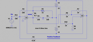
A Balanced Headphone Amp using Positive Feedback.
The attached is another schematic for one channel of the subject. It differs from the one in the previous post in that the sense resistor [0.3 Ohm] is on the side of U1. This required reversing the leads to the diff amp [U2] by comparison. The subjective performance of both options is expected to be similar.
I have assembled this prototype on proto board. I'll attach its picture in the next post.
Attachments
Last edited:
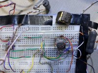
Picture of Prototype
The image of the aforementioned stereo HA prototype is attached.
Please note:
1. Compare the size of the original Signetics NE5532 [on the right] with the smaller-sized TI chip. Super Glue is the smudge on it which had an attached 'nut' heatsink as shown next to it. Does warm up!
2. Each upper OpAmp is the diff amp which samples the magnitude of load current.
3. Each lower OpAmp is the music channel.
4. A star ground is between the two chips.
5. This system sounds great. It is quiet and stable against oscillation. Worth hard wiring.
Will show the image of its PSU.
Best
Anton
Attachments
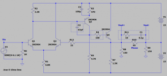
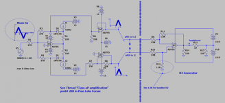
Class aP [or Class B] HA Infused with H2
A one of a kind [different!] Headphone Amp. It demonstrates feasibility of operation, and is a simple tutorial for generating the second harmonic [H2].
The view of the schematic to the left of the $ signs barrier is an analog pulse [aP] generator. Simply said:
1. The depicted input music signal is half wave rectified; or independent analog pulses are thusly generated.
2. The two pulses are buffered [shown] or separately DC amplified.
3. The parent music signal is reconstructed by a bridging load [say a headphone] between output points A and B.
4. The resultant analog pulses are of equal peak amplitude, and each has its time stamp [e.g. 0 to t] for tracking.
The view of the schematic to the right of the $ signs barrier is the H2 Generator.
1. It has the classical diff amp topology; but
2. I deliberately unbalanced the amplitude of the analog pulses at the input ports of the OpAmp. The voltage gain at the output of the OpAmp due to operation at the non-inverting input is higher than that derived from operation at the inverting input.
3. The [*] at the headphone bridged-load signifies the classic polarity= red lead.
4. The positive-going aP [0 to t] has a higher amplitude than the negative aP [t to t1] in the reconstructed signal at the output of the Op Amp. This resultant signal is infused with [+H2] as articulated by Mr. Pass in his articles on H2.
5. Reverse the headphone leads to get [-H2] as taught by Mr. Pass.
The Spice model operates and shows the different operational nuances. Ther stereo system sounds superb; no fooling.
Bet wishes
Anton
Attachments
Last edited:
Consider these two questions.
Q1: Is a DC offset across a headphone a concern/problem?
Q2: Is the signal delivered to your headphone infused with H2?
My answer is No to Q1 and I have a deliberate choice between +H2 or -H2 for Q2.
The attached schematic is a simplified version of that I reported in the previous post. Please note the following as they address the above two questions:
1. Precision Rectifier output aP [t to t1] has an inherent DC offset of +13 mV. By contrast, the output aP[0 to t] does not have an offset.
2. It follows that the phone is sandwiched betwee a net DC offset equal to an absolute value of 26 mV.
3. Thusly, the phone's diaphragm is displaced [away from my ear] from its neutral spot due to the direct current flow through it from this 26 mV DC battery. It is not a trivial displacement; because the magnitude of the listening music I use is 100 mV peak to peak.
4. Mr. Pass reported in his H2 thread Post# 296 that he experimented with deliberate DC offset values across a loudspeaker so as [I understood] to generate H2 from a pristine signal [0H2]exiting the amp.
5. The cone of the loudspeaker or phone's diaphragm is consequently spring-loaded due to this offset. The springiness of the surround is the force hoping to restore the cone back to its neutral position.
6. The signal at the output of uA741 is imbibed with + H2 as I described earlier. Meaning; the peak amplitude of its positive half signal is higher in absolute value than that of the negative-going half signal.
7. Two forces act on the cone which net either a [+H2] or [-H2].
8. My ears got a [+H2] from my stereo prototype as shown for the phones' connection of its polarized leads. I loved its music even with uA741.
9. I liked less the sound of music with the headphones' leads reversed . I suspect too high a [-H2]. A subjectively different sound from [+H2]!
The take-away message is: The subjective quality and my enjoyment of headphones' music depends on important factors like the Op Amp used, pre-polarization of the phones' diaphragms, and the deliberate phase of H2. These forces are readily manipulated. My ears are the only test equipment.
Best
Anton
Attachments
![Class B Headphone Amp Infused with H2[A].png](/community/data/attachments/812/812183-b1a4a596f562fd155a026c83a7d91e2f.jpg)
A different headphone amp [part 1].
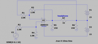
The attached schematic is for the subject HA prototype. Here is how it works:
1. The OpAmp has a differential [diff] topology.
2. The RCA input signal is fed to the non-inverting OpAmp input.
3. The resultant inverted signal at the joined PSUs is fed back to the inverting input of the OpAmp so as to satisfy the "diff" circuit requirement. I had called this junction [Vout current source] because it was derived from the high impedance "opposed BJT collectors" of the output stage.
4. The 32 Ohms load bridges Vout of the OpAmp [voltage source] and [Vout current source]. These two outputs are of equal absolute amplitude and are out of phase.
5. This circuit has a propensity to give 0% THD as shown by Spice's FFT. This status depends on the nature of OpAmp used. The indicated OpAmp shows no H2 or H3. Plug in other OpAmps which can [most of the time] give 0% H2 plus some H3.
6. Sounds great. No hum or instability.
Part 2 will follow.
Best
Anton
Attachments
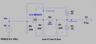
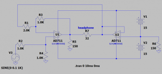
A different headphone amp [part 2].
The prototype schematic in the previous post [#31] showed the phone load bridging a voltage and a correlated current sources.
I am calling this arrangement a "Hybrid Bridge". It has a characterestic sound like a mule has its different performance [strength and weakness] from its parents. I'll post more on the resultant "hybrid sound" in a separate post.
The attached schematic in this post shows the phone load bridging two voltage source amps , like normally done. Here is how it works, and answers the question of what to do with a dual OpAmp like NE5532 and OPA2134 in such circuits using singles:
1. The left-side OpAmp works like the one I showed in the previous post. It is one side of the voltage source bridge.
2. The right-side OpAmp buffers the current source output [center point of PSUs] and is the inverting second side of the bridge.
3. This normal bridging circuit sounds different from that of the "Hybrid Bridge". Discernible.
4. Both prototypes sound great with no hum, buzz or oscillation.
5. SPICE's FFT shows an absent H2 as said in the previous post.
Best
Anton
Attachments
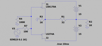
A Complementary Symmetry JFET Headphone Amp
The schematic for this subject prototype is attached. I see this JFET circuit the simplest; albeit potent innovation by Mr. Pass.
1. The 32 Ohm headphone is the "Hybrid Bridge" I already discussed.
2. The actual FETs are SJ74 BL and K170 BL I got from audio diyer "buzzforb" during the fame-days of diyF6. I believe each FET idles at 10 mA.
3. There's no DC offset across the load; a testament to buzzforb's accurate matching.
4. The Grado Labs Model SR80 headphones sound superb with this simple amp.
5. Our diyAudio Store sells such matched FETs.
Best
Anton
Attachments
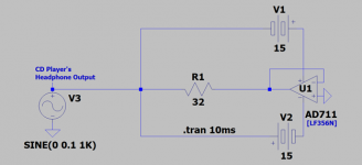
Another HA
I continue to be fascinated with the patent by Mr. Pass: US 4,107,619. It is entitled Constant Voltage -Constant Current High Fidelity Amplifier..
The attached schematic of this prototype works "like" that described above. Please note:
1. I use a CD player as the music source. Its headphone output amp is an important component of this prototype. It operates in state of constant current ~constant voltage [CC~CV], and thus is a high fidelity micro amp.
2. The music current issued by the CD player's HA [input signal] is ~10 Nano Amps per its LTSPICE model.
3. The BJT output transistors of the OpAmp [uA741, or LF356 or OPA134] operate in the Common-Base configuration. The OpAmp is the sole source of the [whole] current flowing thru the phone load.
4. It follows that the CD player's HA corrects [if needed] the performance of the OpAmp which may have its origin in its mA-level current fluctuations.
5. This HA sounds great.
Best
Anton
Attachments
End of thread for now
The HA prototype in the previous post was up-sized in power. The resultant power amp [in stereo] sounds high fidelity.
I am shifting gears from this HA thread to post in this other thread in the Pass Labs Forum which is entitled DIY the device of US Patent 4,899,387. This patent is by/for Mr. Pass.
I am currently using this power amp in an application to manage reverberant bass energy in my listening room.
Best
Anton
- Status
- This old topic is closed. If you want to reopen this topic, contact a moderator using the "Report Post" button.
- Home
- Amplifiers
- Headphone Systems
- Different headphone amps