
Sorry I'm here now hahaha
Yeah that's my PCB, I originally took a schematic from AMB but then changed it to a simple RC delay circuit, something like this
And it's similar but it's an XPPower ECL10US12-E (10w) since those don't have a maximum load capacitance
Yeah that's my PCB, I originally took a schematic from AMB but then changed it to a simple RC delay circuit, something like this
And it's similar but it's an XPPower ECL10US12-E (10w) since those don't have a maximum load capacitance
Last edited:
Yeah that's my PCB, I originally took a schematic from AMB but then changed it to a simple RC delay circuit, something like this
And it's similar but it's an XPPower ECL10US12-E (10w) since those don't have a maximum load capacitance
Excellent, thank you very much
 .
.Do the XP Power units really have no load capacitance limit, or do they just not specify it in the data sheets?
After a very promising prototype, I will order some PCB's and build a better version...also my friend knauf1919 designed a nice power supply for this tiny amp....I invite him to post the final version of the PCB project if he wants so... Even I can get modern BD139 from the online stores, I have a bunch of old stock TFK BD137, their gain is around 80....could these be suitable instead BD139? From the datasheet there's no other difference other than the maximum supply...
Also I have in mind (but seems quite overkill here) to use a pair of BD177, new old stock, made by Motorola. In this case the gain is above 100....and Ic raises to 3A.
What gain did you also meassure concerning BC550-560? Mine have above 500....isn't a bit suspect higher? The transistors are from modern/contemporary era...this high gain makes me think of using those old transistors with smaller gain....should I search for replacements with reduced gain, like BD327-337?
Last edited:
The hfe of mine were in the 400-500 range and no issues.
I've got some BC327/337 on order as well as the TTC004B which seems to be a good alternate for the BD139. They are backordered at the mo, but when they turn up I'll swap some over and hopefully run some measurements to see how they compare.
I've got some BC327/337 on order as well as the TTC004B which seems to be a good alternate for the BD139. They are backordered at the mo, but when they turn up I'll swap some over and hopefully run some measurements to see how they compare.
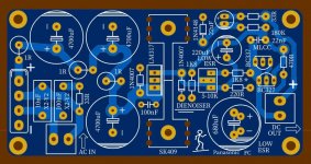
...also my friend knauf1919 designed a nice power supply for this tiny amp....I invite him to post the final version of the PCB project if he wants so...
It's nothing special. It's the DieNoiser version (I like the name) of tombo56.
Attachments
Thank you for the reply, I will wait and order also the pair for TTC004B, which is TTA004B...maybe I will get more luck for good pairs...all recently bought BD139-140 are a lot different from PNPs to NPN, even if they have the same or close hFE between the same polarity types....TTC004B which seems to be a good alternate for the BD139...
It could be interesting if this schematic can be developed for higher supply...maybe at 24V or at least 20V it could drive the 300 ohm or higher headphones. I listened to my prototype with DT880 (250 ohm version) and the power is enough for me, but the volume was at about 3 o clock for moderate listening level. The source is a DAC output, I think it's around 0.7V output (standard line level).
My amp needs about 150mA for two channels, did you monitor the current in yours? (this question is for everyone...sorry if already answered earlier...).
..I will wait and order also the pair for TTC004B, which is TTA004B...maybe I will get more luck for good pairs..
Sorry I don't understand. The TTC004B replaces the BD139. This amp doesn't use the complementary BD140, so you shouldn't need the TTA004B.
It could be interesting if this schematic can be developed for higher supply...maybe at 24V or at least 20V it could drive the 300 ohm or higher headphones. I listened to my prototype with DT880 (250 ohm version) and the power is enough for me, but the volume was at about 3 o clock for moderate listening level. The source is a DAC output, I think it's around 0.7V output (standard line level).
Would be interesting. I paralleled a pair of boards and had good results, but the headphones I drive aren't quite as difficult as the Beyerdynamics.
My amp needs about 150mA for two channels, did you monitor the current in yours? (this question is for everyone...sorry if already answered earlier...).
Yep, mine all use around 90-100mA per channel plus a bit extra for filtering / voltage regulation.
Are you getting the full 12v at VCC or dropping some by power supply filtering?
Hi carageae,
If you try higher supply voltages, I'd start by increasing the values of the Emitter resistor divider string.
And maybe plan a front panel note so *somebody*(which likely would be me!) doesn't expect the same performance when plugging in lower impedance 'phones.
Wow, avtech23, that is an excellent body of work -- building and testing and posting! (Sorry it took me a month to say so ..)
Cheers
If you try higher supply voltages, I'd start by increasing the values of the Emitter resistor divider string.
And maybe plan a front panel note so *somebody*(which likely would be me!
) doesn't expect the same performance when plugging in lower impedance 'phones.Wow, avtech23, that is an excellent body of work -- building and testing and posting! (Sorry it took me a month to say so ..)
Cheers
Last edited:
Sorry I don't understand. The TTC004B replaces the BD139. This amp doesn't use the complementary BD140, so you shouldn't need the TTA004B.
***
Are you getting the full 12v at VCC or dropping some by power supply filtering?
OK, the PNP is for another project, from Silicon Chip magazine, using BD139-140 in the finals. Sorry for the confusion...
I get exactly 12V after filtering with 2 caps of 2200uF and a 10 ohm resistor the output of a power supply delivering 13.5V "as is".
Now I tested the amplifier with a SMPS, salvaged from a vintage analog video camera adapter, made by Sony. There is no noise at all and the sound seems more detailed.
In the future I will build these amplifiers with the power supply described above - let's wait and see....
About the supply voltage raise...apart from the use of high(er) impedance headphones, I intend to use this amplifier, if possible, with some small desktop speakers...as is, I think I could use with some special speakers I have - 50 ohms speakers - but it could be more interesting to use normal speakers. I don't expect much power, just to replace the built-in TV speakers permanently...
Last edited:
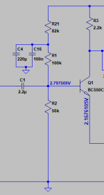
I know I am rather late to the party but I would like to suggest a small improvement to this design. As it stands, its PSRR is quite poor simply because the first stage is biased directly from the supply. Any noise on the supply is fed straight to the input and care is needed with the PCB layout to ensure output stage signal currents do not induce voltages onto the supply feeding the bias resistors.
To fix this I would suggest using a decoupled potential divider for generating the required bias voltage and then feeding this to the base of the first transistor via a suitable value resistor.
Cheers
ian
To fix this I would suggest using a decoupled potential divider for generating the required bias voltage and then feeding this to the base of the first transistor via a suitable value resistor.
Cheers
ian
Hi Ian, it's never too late to join this party!
Thanks for your suggestion. Looking at the circuit, it makes total sense that whatever noise gets past the PSU filtering will manifest in the input of the BC550.
I've had a play in the sim and this change seems to make quite a difference when I inject a sine wave into the DC supply:
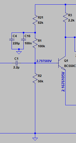
Is that along the lines of what you are thinking?
Thanks for your suggestion. Looking at the circuit, it makes total sense that whatever noise gets past the PSU filtering will manifest in the input of the BC550.
I've had a play in the sim and this change seems to make quite a difference when I inject a sine wave into the DC supply:
Is that along the lines of what you are thinking?
Attachments
- Home
- Amplifiers
- Headphone Systems
- 3 Transistor HP Amplifier with low dist