Then that explains it.Your heatsinks are more substantial than what I use.
I have a little plate with low Rth between the BD139 and plate (thin foil) and ~0.7W on it;
the resistors get obviously cooled through the PCB at least a little.
I try to use >=1mm tracks whenever I can; and yes, the PCB is pretty warm too.


Hi Bucket,
If the green traces are component-side, you're going to have trouble soldering the output capacitors.
Cheers
Red is component-side


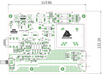
Did a V1.1 of my PCB. Suggestions and criticisms always welcome
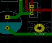
L_out trace is running too close to the heatsink mounting stud.
Attachments
Last edited:

I feel lonely, I'm the only one so far who's done a board with SMD components
Beautifully compact & symmetric! That´s a very nice layout.Another one to add to the "basket" of designs. Test Board...
What SW is that? Looks nice for perfboard layouting. (I use Lochmaster which is OK too)
Are we already at 1 layout/page?
You are correct. We shall all post our implementations, me included of course.Lots of pcb variants and just a few implementations.
Shouldn´t have made a "temporary enclosure" because now I can´t stop listening!
Literally the only improvement I can think of for this amp, is to add an optional crossfeed. The amp is revealing enough that certain recordings are "tough" to listen to. Of course that´s an inherent disadvantage of headphones in general. No blame on this beautiful amp.
Ah dammit, hopefully it'll be fine since it's on the underside. Will fix for next revision.L_out trace is running too close to the heatsink mounting stud.
Beautifully compact & symmetric! That´s a very nice layout.
What SW is that? Looks nice for perfboard layouting. (I use Lochmaster which is OK too)
It is not a special perfboard software. I use Easy-Eda.
The design is not original and is inspired by the others made by prasi and avtech23.
Please go ahead, I´d love to hear your opinion, anytime.
BR
Jens
Regarding this discussion ...
I was thinking that just putting both ,headphone amplifier and power amplifier inputs in parallel, can bring minor changes. I don't know, maybe it's stupid to consider that.
Made a new layout (100mmx70mm) With onboard power supply (CRC and LM317)
Still listening to my breadboard version, sounds great for such a simple and clean design
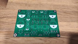
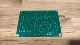
Boards have arrived and are looking great
Next week I can get the rest of the components.
Attachments
Last edited:
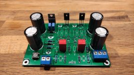
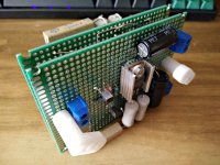
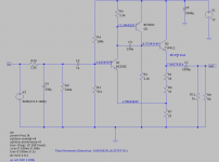
Finally I got time to finish the amplifier. Some values I changed to ones that where available to me after simulating the circuit and I used a TIP41C transistor.
R1, R6 and R7 where originally specified for max 1W but they got way too hot. So I swapped them for matched 5W ones (that is, 5W by the looks of it). The temperature of these resistors are now ok.
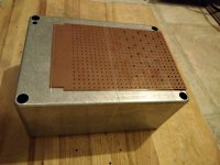
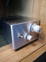
I wanted to use a small enclosure of 10.5 x 14.5 x 7.5cm but I also wanted the two PCBs leaving some space for experimenting if necessary. To fit the PCBs in the enclosure I 'sandwiched' them.
I drilled ventilation holes in the bottom and top of the enclosure using a template made from an old PCB.
I made the input and output at the back of the enclosure. Three reasons for that: I use a correction filter for my Beyerdynamics DT770 Pro 80 ohm headphones, I do not like the looks of the headphone input and there is no space at the front of the enclosure.
The audio carrying cables in the enclosure are made of cat-5 UTP.
There is no led, I prefer not to be distracted but only by the quality of the amplifier as it is sitting in front of me next to my computer screen.
My right ear is slightly worse than the other so I use a balance potmeter at the front to compensate for that. B.t.w. listening to some recordings I suspect I am not the only one...
A switched power supply of 12V is used. No filter necessary, it is silent.
Regarding the quality the only comparison I can make is comparing it to a simple opamp headphone amplifier using a NJM4556 set to class A with some other bells and whistles. I did not expect such a big difference: overall it sounds a lot nicer (listening to lossless files on my computer via an old Music Streamer II USB DAC).
Thanks Lineup!
R1, R6 and R7 where originally specified for max 1W but they got way too hot. So I swapped them for matched 5W ones (that is, 5W by the looks of it). The temperature of these resistors are now ok.
I wanted to use a small enclosure of 10.5 x 14.5 x 7.5cm but I also wanted the two PCBs leaving some space for experimenting if necessary. To fit the PCBs in the enclosure I 'sandwiched' them.
I drilled ventilation holes in the bottom and top of the enclosure using a template made from an old PCB.
I made the input and output at the back of the enclosure. Three reasons for that: I use a correction filter for my Beyerdynamics DT770 Pro 80 ohm headphones, I do not like the looks of the headphone input and there is no space at the front of the enclosure.
The audio carrying cables in the enclosure are made of cat-5 UTP.
There is no led, I prefer not to be distracted but only by the quality of the amplifier as it is sitting in front of me next to my computer screen.
My right ear is slightly worse than the other so I use a balance potmeter at the front to compensate for that. B.t.w. listening to some recordings I suspect I am not the only one...
A switched power supply of 12V is used. No filter necessary, it is silent.
Regarding the quality the only comparison I can make is comparing it to a simple opamp headphone amplifier using a NJM4556 set to class A with some other bells and whistles. I did not expect such a big difference: overall it sounds a lot nicer (listening to lossless files on my computer via an old Music Streamer II USB DAC).
Thanks Lineup!
Attachments
-
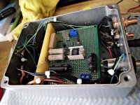 11. the internals.jpg417.7 KB · Views: 206
 -
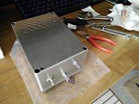 10. fixing external controls and input.jpg313.3 KB · Views: 155
 -
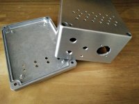 9. holes drilled, brushed case.jpg292.4 KB · Views: 136
 -
 8. drill template ventilation holes.jpg293.9 KB · Views: 168
 -
 6. PCB III.jpg361 KB · Views: 167
 -
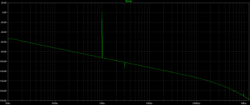 3. FFT.png24.4 KB · Views: 122
 -
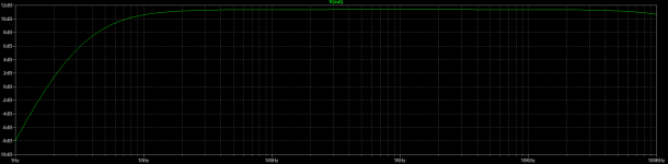 2. freq.png20.4 KB · Views: 398
 -
 1. schematics.png67.7 KB · Views: 432
 -
 12. the result.jpg470.3 KB · Views: 226
I meant which fabrication house. JLCPCB, PCBWay etc?
Ah sorry. Jlcpcb. 7€ including shipping for 5 boards. Only took 2 weeks for the boards to arrive.
- Home
- Amplifiers
- Headphone Systems
- 3 Transistor HP Amplifier with low dist