The one challenge (I can think of) to driving both at all times -- if the unused amp section will be powered down when not used
Cheers
Very good observation and must be put into practice.
My question was more related towards why Knauf1919 doesn´t like to see both amp inputs in parallel to the preamp-out.
Well, we all have our fixations in our brains.
)
I wanted to do something practical before I could give an objective answer. Looks like I can't find time to do that.

Thus hackers can use your mobile phone and laptop to attack other devices and to disguise themselves.
I do not know how BT works for audio streaming, may be these concerns are already taken care of.
BT is probably the most complicated, buggy, and least understood communication protocol in consumer electronics.
In concept, it "could" be possible to lock it down to ONLY accept streaming music. In practice, I have never seen any fine user control of what it would accept.
Normally you have to 'connect', some human action like keystrokes, to open a BT link. However I know there are bugs and hacks, so this is not always needed.
It used to be BT's saving grace that it was short-range. The hacker almost had to be in your house. But I am near a dozen BT devices now, and I do not know what they say to each other. My strange neighbors here are too far for BT (but see Bluesniping), but if I lived in town I could have strange BT devices on all six sides.
bluetooth vulnerabilities list - Google Search
Bluesnarfing - Wikipedia
Bluesniping - Wikipedia
Bluebugging - Wikipedia
Last edited:
Sorry if my writing wasn´t clear.I wanted to do something practical before I could give an objective answer. Looks like I can't find time to do that.
Please go ahead, I´d love to hear your opinion, anytime.
BR
Jens
Your project sounds interesting BTW.
You should document it here!
I have a Raspberry in some crate thats collectin dust;-)
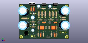
I have posted some details in another thread. Here is just top level design:
https://www.diyaudio.com/forums/attachments/class-d/929113d1615051089-infineon-ma12070-class-amp-jpg
Instead of O2 I'll use the amp from this thread.
The audio signal (USB) will come to that integrated amp from the digital source which is also based on Raspberry Pi:
https://www.diyaudio.com/forums/pc-based/360380-nas-streamer-2.html#post6543671
I'll use the same type of enclosure and display.
Thank you very much. Your system is really nice. Love the detail, passion and even documentation you put into it!I have posted some details in another thread....
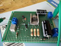
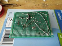
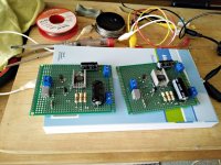
I finally made the amplifier on two perfboards.
Although the frequency range is now limited I like to keep connections on the pcb as short as possible, a bit point to point, with the 330pF capacitor close to the BC560C. I tend to approach this as a HF circuit. However in this case I made the connections not too short to leave some room for adjustments if needed.
The three resistors at the emittor of the TIP41C get hot. I probably have to get used to that as I only made opamp based amplifiers before. I lifted these resistors of the board.
The heatsink for the TIP41C is small but it may help cooling it down. It only gets slightly warm.
I also lifted the heatsink a bit of the perfboard by putting a metal ring between the heatsink and the perfboard.
Attachments
Last edited:
The voltages measure about the same as the simulation.They are at the limit.
The 33 ohm ones dissipate 326mW, the 22 ohm resistor dissipates 199mW. That is within the limit of the resistors that I used.
However they become hot to the touch. Measuring the temperature with my finger is as reliable as eyeballing the weather forecast by looking at the clouds I guess. I am not sure they are too hot.
Post #10, 11, 13, 16 and 81 hint at these resistors being warm (hot?) and suggest using 1W.
I am not experienced with these kind of circuits so it occured to me they are too hot to touch.
Last edited:
The 33 ohm resistors should dissipate around 270mW, the 22 ohm a bit less - about 180mW.
1W is within specs, but will run hotter for sure.
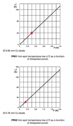
I used the Vishay PR02 series because the 2W resistors heat up almost half as much as the 1W:

Resistors such as these are designed to heat up, and can be run quite hot:
"The maximum permissible hot-spot temperature is 205 °C for PR01, 220 °C for PR02 and 250 °C for PR03".
Although the resistor will be comfortable running at high temperature, it is always good to consider the impact it will have on neighbouring components and the PCB itself when selecting these components. Having a set of resistors running towards 100 degrees, next to electrolytics rated at 85 degrees, for instance, would not promote longevity.
1W will be ok, but keep them off the board, in a vented enclosure and away from anything sensitive to heat (such as electrolytics).
1W is within specs, but will run hotter for sure.
I used the Vishay PR02 series because the 2W resistors heat up almost half as much as the 1W:
Resistors such as these are designed to heat up, and can be run quite hot:
"The maximum permissible hot-spot temperature is 205 °C for PR01, 220 °C for PR02 and 250 °C for PR03".
Although the resistor will be comfortable running at high temperature, it is always good to consider the impact it will have on neighbouring components and the PCB itself when selecting these components. Having a set of resistors running towards 100 degrees, next to electrolytics rated at 85 degrees, for instance, would not promote longevity.
1W will be ok, but keep them off the board, in a vented enclosure and away from anything sensitive to heat (such as electrolytics).
Attachments
Thanks for the information Avtech23. I shall replace these resistors for 3W ones and move them a bit away from the output capacitor.1W will be ok, but keep them off the board, in a vented enclosure and away from anything sensitive to heat (such as electrolytics).
I use 0.6W metal resistors and don´t find them too hot.
Can keep my finger on them; not very scientific I know but ~270mW should be OK. You can always double them up and use 2x68R in parallel or similar.
Both output transistors (~350mW each) are on a little aluminium plate and that I can´t touch for very long. (and that´s in a 20°C room)
They say though that europe is gonna get colder with climate change and all,
so I might be alright in the end
I tend to agreeI do not agree with components that operate at more than max. 45 ° C.
Where did you read Europe is getting colderI use 0.6W metal resistors and don´t find them too hot.
Can keep my finger on them; not very scientific I know but ~270mW should be OK. You can always double them up and use 2x68R in parallel or similar.
Both output transistors (~350mW each) are on a little aluminium plate and that I can´t touch for very long. (and that´s in a 20°C room)
They say though that europe is gonna get colder with climate change and all,
so I might be alright in the end
It is just the other way around with the one I built, I can keep my finger on the transistor but not on the resistors. Maybe because I changed the base resistor of the output transistor to 2.2k instead of 1.8k, and I used a TIP41C. However the measurements are not that much different compared to the original if I look at the simulation.
Last edited:
Your heatsinks are more substantial than what I use.It is just the other way around with the one I built
I have a little plate with low Rth between the BD139 and plate (thin foil) and ~0.7W on it;
the resistors get obviously cooled through the PCB at least a little.
I try to use >=1mm tracks whenever I can; and yes, the PCB is pretty warm too.
- Home
- Amplifiers
- Headphone Systems
- 3 Transistor HP Amplifier with low dist