Transistors are BC550C and BC560C. Because C-type has higher gain.Hello!
In some schematic the output coupling cap is 1000uF and others in 2200uF. Which one is recomended? And BC550-560 as B or C type? Thank you.
I was asked about BC547 / BC557.
Both of those can be used = BC547B and BC557B.
Original circuit had 1000uF. And this will work.
If you have 2200uF you should use this.
I now recommend 2200uF for 32 Ohms headphones.


The headphones are 32 ohms. I have a USB DAC that's powered by a 5V linear PS. .. thinking of a veroboard point-point implementation.
Hi auriga2001in,
Doesn't your linear supply have a higher voltage pre-regulator, that you could tap off for this HPA?
It would be a lot to ask -- even if you had the luxury of custom ICs designed for the lower voltage -- to achieve quality sound using only 5V.
")
Cheers
 Moderators added note, member prasi has indicated an error in this post, please refer to post #152 for correction
@prasi and @joensd
Your beatiful work makes me happy.
It is fantastic
All the best to India and Germany from me in Sweden
Hello line up and joe,
thanks for your kind words.
Thanks for the design and association.
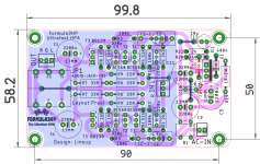
to anyone interested,
Here are gerbers and pdf files. Untested but should work very well.
regards
prasi
Attachments
Last edited:
OMG
You saved me from a major fiasco. Thanks avtech .
.
I request moderators to delete post #150.
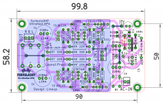
here are correct files.
You saved me from a major fiasco. Thanks avtech
.I request moderators to delete post #150.
here are correct files.
Attachments
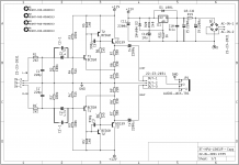
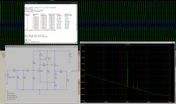
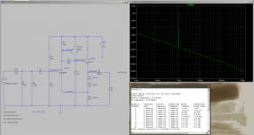
I changed the values according to the components that I have laying around. And experimented a bit with LTSpice.
How does it look? Please be gentle, I do not have much expericience with LTSpice.
B.t.w. the circuit seems to be pretty tolerant of value changes.
How does it look? Please be gentle, I do not have much expericience with LTSpice.
B.t.w. the circuit seems to be pretty tolerant of value changes.
Attachments
Last edited:
here are correct files.
Thank you prasi! Is this free for any one to use? I am thinking of placing an order from some online PCB maker.
I changed the values according to the components that I have laying around. And experimented a bit with LTSpice.
How does it look? Please be gentle, I do not have much expericience with LTSpice.
B.t.w. the circuit seems to be pretty tolerant of value changes.
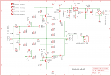
Looks to operate ok, but make sure you check the current values of each transistor to make sure they are within spec.
If you give the mouse over a transistor, it should show you the value in the bottom corner of the screen. You can also right click on wires and add datapoints that show voltages of the node. These can also be edited to show current or power instead.
Yeah, post your results.If interested I can post the results.
Curious how your breadboard build works.
Can´t wait to try that amp myself!
- Home
- Amplifiers
- Headphone Systems
- 3 Transistor HP Amplifier with low dist