Just a quick update on this one.
I've had the prototype running for a little while. I added a simple passive 2nd order low pass filter to the power supply to improve the noise rejection.
It did sound very good, and able to drive my 32ohm and 38ohm headphones quite nicely, and wasn't heating up excessively. With no input, the amp was silent.
But, the amp was recently exhibiting low frequency oscillations (tuk...tuk...tuk..tuk..).
During the last listening session, the amp distorted heavily and then carried on playing. The power resistors and BD139 are now all cold while the amp runs.
The amp does still make music, but distorts at medium volume levels. I haven't performed the necropsy yet, but it will be interesting to see what the issue is.
I made a new layout and had everything ready to send to fab, but I'm gonna put a pause on that one until I know why this prototype didn't survive for long.
Attachments
Another quick update.
The issue I had seems to have been caused by a failing power supply. It worked fine again for days and now it's making a pulsing sound and the outputs are cold again.
I swapped in a 9v supply and immediately the amp works again no issues and is dead silent with no input.
I've been listening to this one for a while and am really impressed with the performance for such a simple circuit. I am driving a pair of 38ohm Audio Technika ATH-M50X with no issues. Vocals are clear, bass is about as good as these headphone will produce. Stringed instruments have a nice clarity and detail to them.
I intend on re-running the measurements once I've got a replacement PSU organised. I'll also reorganise the input filter and see if that shows a measurable or audible change.
And in the meantime, I'm waiting on an O2 amp to arrive from the States to give me a 'proper' reference amp to compare with.
Hi Marin.
The prototype had been running fine for a while with a different power supply so I have progressed with this one.
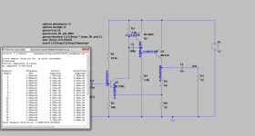
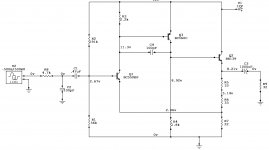
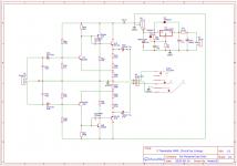
I left the circuit as is other than adding an LM317 regulator for the PSU. Minimum ~18v in and regulated down to 12v. I haven't had any issues driving it with either mobile phone or DAC, so I left the input alone for now.
I went ahead and got PCBs made with the following scheme:
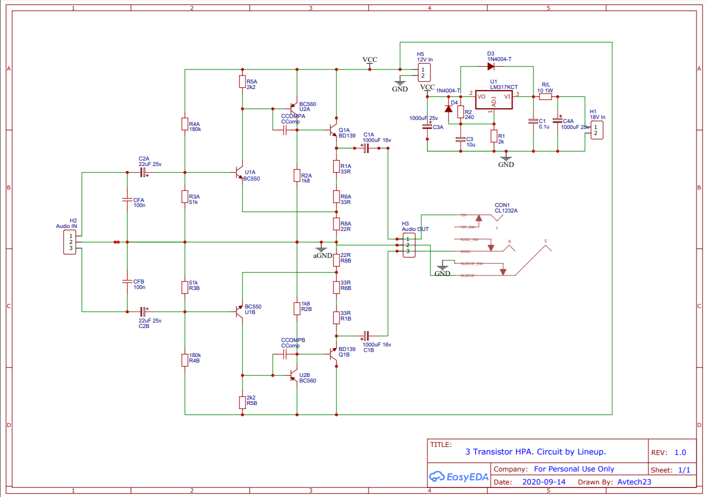
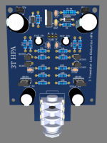
This was the final layout:
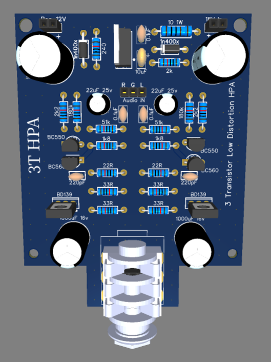
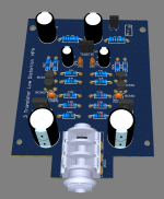
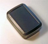
I shaped it to fit a Bud Enclosures HH-3643:
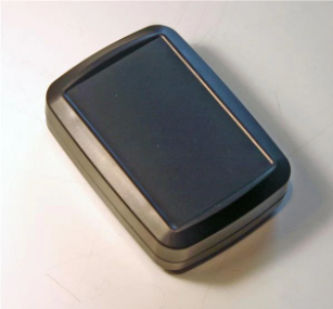
And this is the finished result:
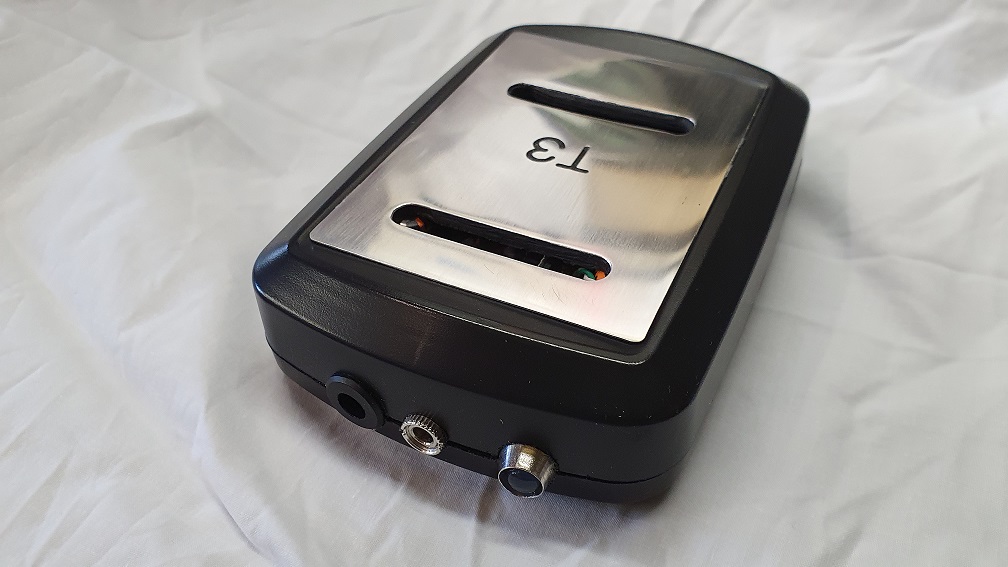
(This is the second unit. I put the LED in to cover a mis-drill on this one )
)
The prototype had been running fine for a while with a different power supply so I have progressed with this one.
I left the circuit as is other than adding an LM317 regulator for the PSU. Minimum ~18v in and regulated down to 12v. I haven't had any issues driving it with either mobile phone or DAC, so I left the input alone for now.
I went ahead and got PCBs made with the following scheme:
This was the final layout:
I shaped it to fit a Bud Enclosures HH-3643:
And this is the finished result:
(This is the second unit. I put the LED in to cover a mis-drill on this one
)Attachments

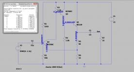
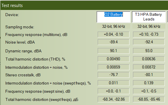
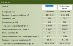
I have taken some measurements with a 250ohm load and got the following:
Noise -92.4dBA
Dynamic Range 93 dBA
THD 0.00636%
I don't trust RMAA so I used my O2 with the same load and setup to act as a comparison. Listed THD for the O2 is 0.0016%, 0.0049% measured, so the measurements made should at least be in the correct order of magnitude.
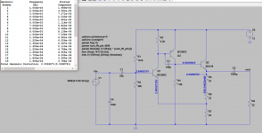
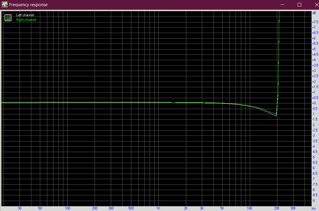
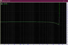
The frequency response falls away around 1dB between 10-20KHz:
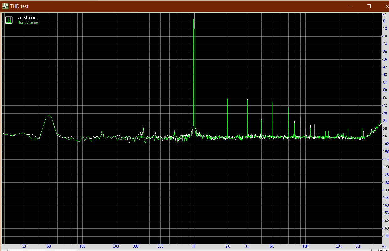
The distortion is dominant 3rd:
This is a finished board:
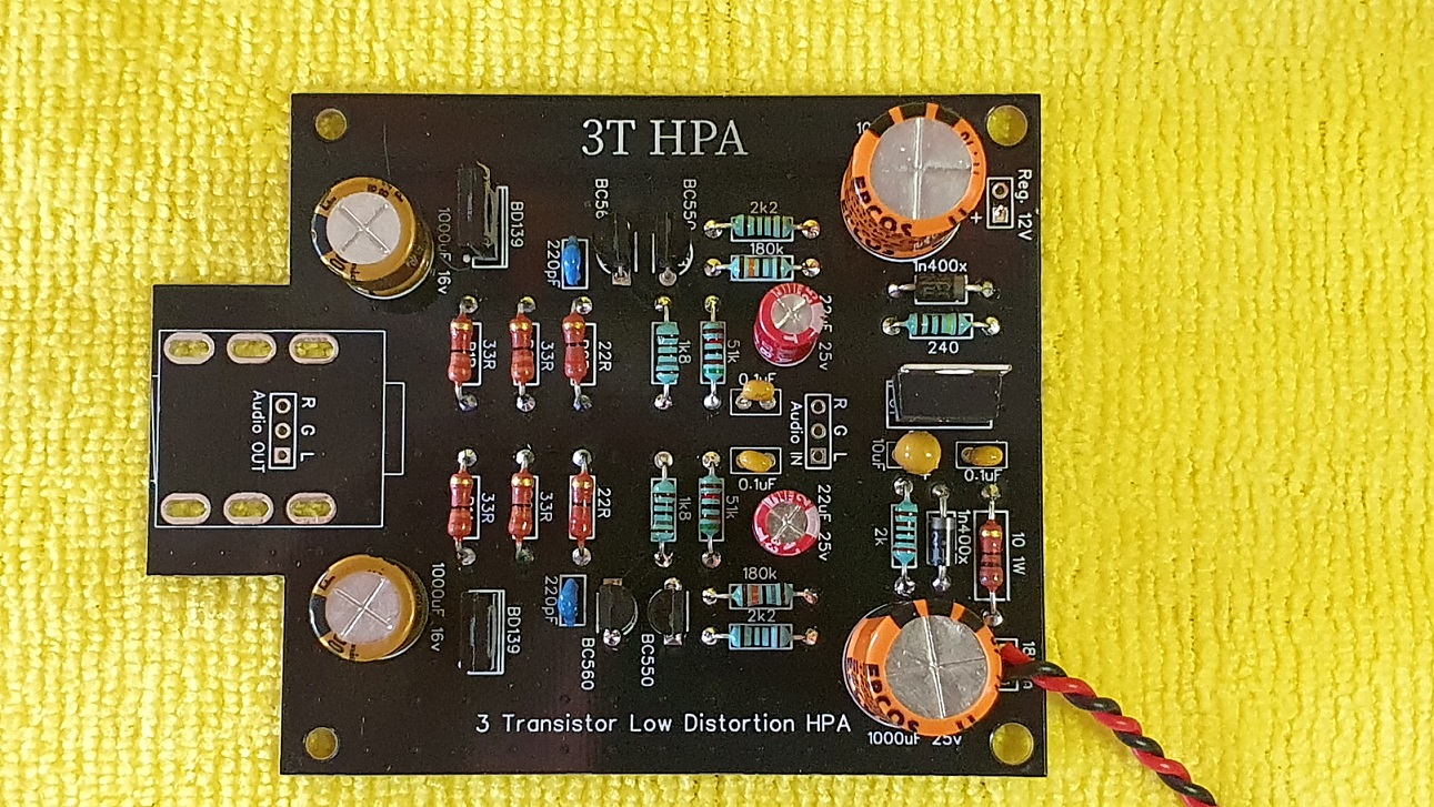
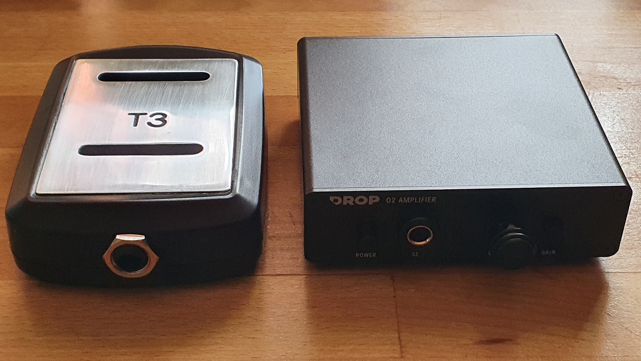
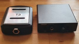
And here is the unit with the O2 for scale:
********************************************
Sound wise, this little unit sounds really good to me. Vocals are clear and bass is good. The falling high frequency response seems to reduce fatigue, particularly when listening to female vocals for long periods. It drives my 38 ohm headphones with ease and has plenty of headroom available.
I used a heatsink on the LM317, but it is within specs to leave off if desired (only passing ~200mA). Minimum stable voltage for the LM317 is around 16-17v (usually about 4v above the regulated voltage, depending on current draw), so 18v was the nearest cheap PSU. An old spare 19v laptop charger would probably work well.
I didn't heatsink the BD139 and they got to ~60deg Celsius with ambient above 30deg, which should be fine.
Noise -92.4dBA
Dynamic Range 93 dBA
THD 0.00636%
I don't trust RMAA so I used my O2 with the same load and setup to act as a comparison. Listed THD for the O2 is 0.0016%, 0.0049% measured, so the measurements made should at least be in the correct order of magnitude.
The frequency response falls away around 1dB between 10-20KHz:
The distortion is dominant 3rd:
This is a finished board:
And here is the unit with the O2 for scale:
********************************************
Sound wise, this little unit sounds really good to me. Vocals are clear and bass is good. The falling high frequency response seems to reduce fatigue, particularly when listening to female vocals for long periods. It drives my 38 ohm headphones with ease and has plenty of headroom available.
I used a heatsink on the LM317, but it is within specs to leave off if desired (only passing ~200mA). Minimum stable voltage for the LM317 is around 16-17v (usually about 4v above the regulated voltage, depending on current draw), so 18v was the nearest cheap PSU. An old spare 19v laptop charger would probably work well.
I didn't heatsink the BD139 and they got to ~60deg Celsius with ambient above 30deg, which should be fine.
Attachments


Last edited:
Thanks Marin.
How did your breadboard attempt work out?
The result was surprisingly good. I really like the way it sounds. That's why I said in post # 10 that the resistors are heating up.
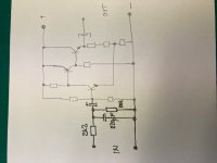
I changed R4 to an E24 standard resistor value because they are easier and cheaper to get hold of. R3 was adjusted from 56k to 51k to restore the voltage set point. The sim didn't show any increase in the distortion figures by doing so.
Just another note, I tried various compensation capacitors and found that I got oscillation with anything below 220pF. From memory, I think I stuck with the 330pF in that position.
Last edited:
Hi Avtech23,
Nice work! You have been busy - I just happened on this thread today. I am not sure why you have 100nF cap to ground on your inputs? Usually an input RFI filter consists of something like 2k2 in series and 220pF to ground. That’s a 330kHz low pass corner frequency good enough for music transients and keeps RF out. You don’t have an input series resistor so it may depend on your source series impedance. But let’s assume it’s a typical RCA type opamp output with 600ohm impedance. Combined with 100nF is a 2.7kHz low pass corner frequency. You will heavily attenuate the highs for typical sources.
Another thing to add is a 100k resistor in front of the input cap to ground. That helps to discharge the input cap and reduces hum pickup when the input is disconnected.
Related to the topic of 3 transistor headphone amps, there is a hot running Class A design by Diegomj called the American Beauty that looks very interesting.
1W - 7 Components American Beauty Buffer
Very simple but predicted performance is outstanding. With big TO247 MOSFETs +/-24v and 625mA bias it can drive 5w into 32ohms. But at the cost of 30w dissipation per channel. Modest 300mA bias and +/-22v will satisfy 99.9% of folks for only 13w per channel dissipation. Even 135mA bias and +/-15v supplies with little TO220’s will drive 4vpp into 50ohms with 0.003%THD. Only 4w dissipation. You can use many of your existing nicely regulated HPA PSU’s for that.
Much more manageable. Fun stuff though.
Last edited:
- Home
- Amplifiers
- Headphone Systems
- 3 Transistor HP Amplifier with low dist