Nah, for me its always been about getting exactly what I want. there are few things we build that would save much money. Actually the foil SMD resistors seemed like one of the more reasonable parts in the BOM to me ...the $2400 in mil tantalum bypass caps on the other hand and several hundred just on surface mount nuts ...
it's an amazing project. Very impressive. I love the symmetry. There are certainly areas I would do differently and given the same budget, but thats the point of DIY.
How long does a charge last? 3 months?
thank you ^V^
It can continue use 14 hours after fully charge.
Because I use the VICOR module constant power consumption to heat capacitor array.
Don't like fans as they seem to be designed to break down. Also the noise does IMO not belong in a living room.
Stunning design and hats off for your perseverance!!
I love Modularize design.
I can easily upgrade and modify by replace a new module if any Inspiration come in my brain.
Boss, this project, are you going to share, sell or use it for other purposes
Not for sale.
Self use only.
The purposes I design new machine every year is learn new techniques and Improve design skills.


Last edited:

Total 1396 parts for single amplifier.
Color me impressed! You should have no problem landing a hardware DE job anywhere in the world with this in addition on your resume'.
I like the attention to details with the little component manufacturer logos and your name in script on the PCB. Most would be exhausted by the rest of the design to bother. Looks like you feel it's part of the fun!
I've always been interested in the history of the LiPo battery. I think there's a reason why a Tesla battery is made up of a bazillion (7,104) 18650 cells - and it's a "WFB" one, not an engineering one. In China, things are probably different in terms of manufacture ability. If so, good for you and it must be fun to work designing batteries / systems that use them w/o restriction.
Thank you
I love the LOGO details too.
All the small thing combine together to make perfect function and beautiful music.
That's why I love doing design.
even the ASM2575 foil resistor soldering direction.

It need check direction before soldering on PCB by use high magnification magnifier

Because the foil resistor structure can influences Multiple frequency crosstalk
Need make sure the direction are the same.

I love the LOGO details too.
All the small thing combine together to make perfect function and beautiful music.
That's why I love doing design.
even the ASM2575 foil resistor soldering direction.
It need check direction before soldering on PCB by use high magnification magnifier
Because the foil resistor structure can influences Multiple frequency crosstalk
Need make sure the direction are the same.
Last edited:

I love the battery level meter animated shown when power on.
Battery voltage meter - YouTube
Love this detail. You didn't have to do this, but you did
All the Consumer product like smart phone / Notebook / Tablet
we use Multiple cell in Series together to creat high voltage (for lower operating current)
Lower current mean lower Power loss.
and Multiple cells in parallel together to creat high capacity
But because of the difference in battery internal resistance.
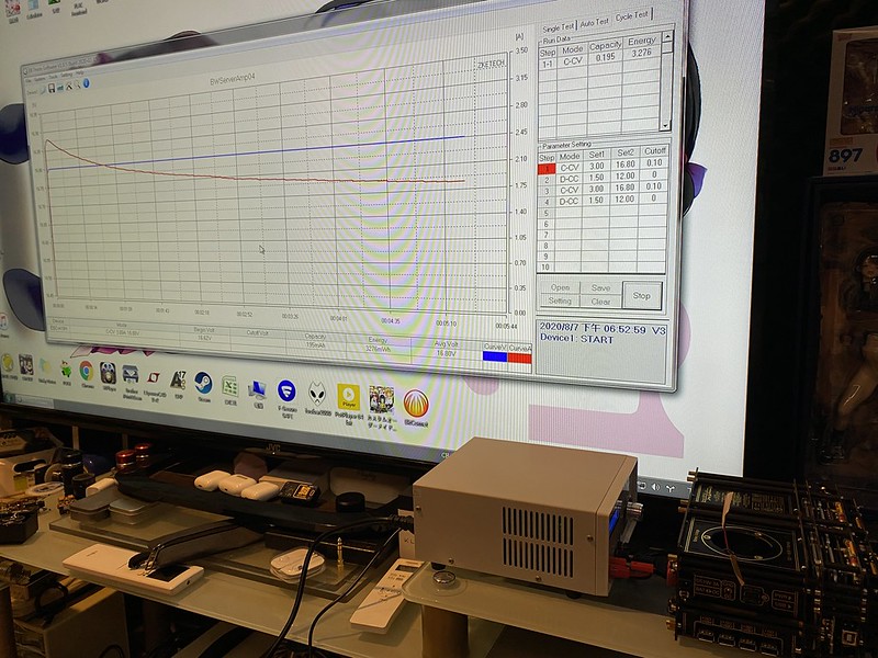
The battery protection / Gauge Ic need to Forecast discharge curve and Computing capacity
So we call this "Charge/discharge process" = "learning process"
And call the "Charge/discharge machine" = " Learning machine"
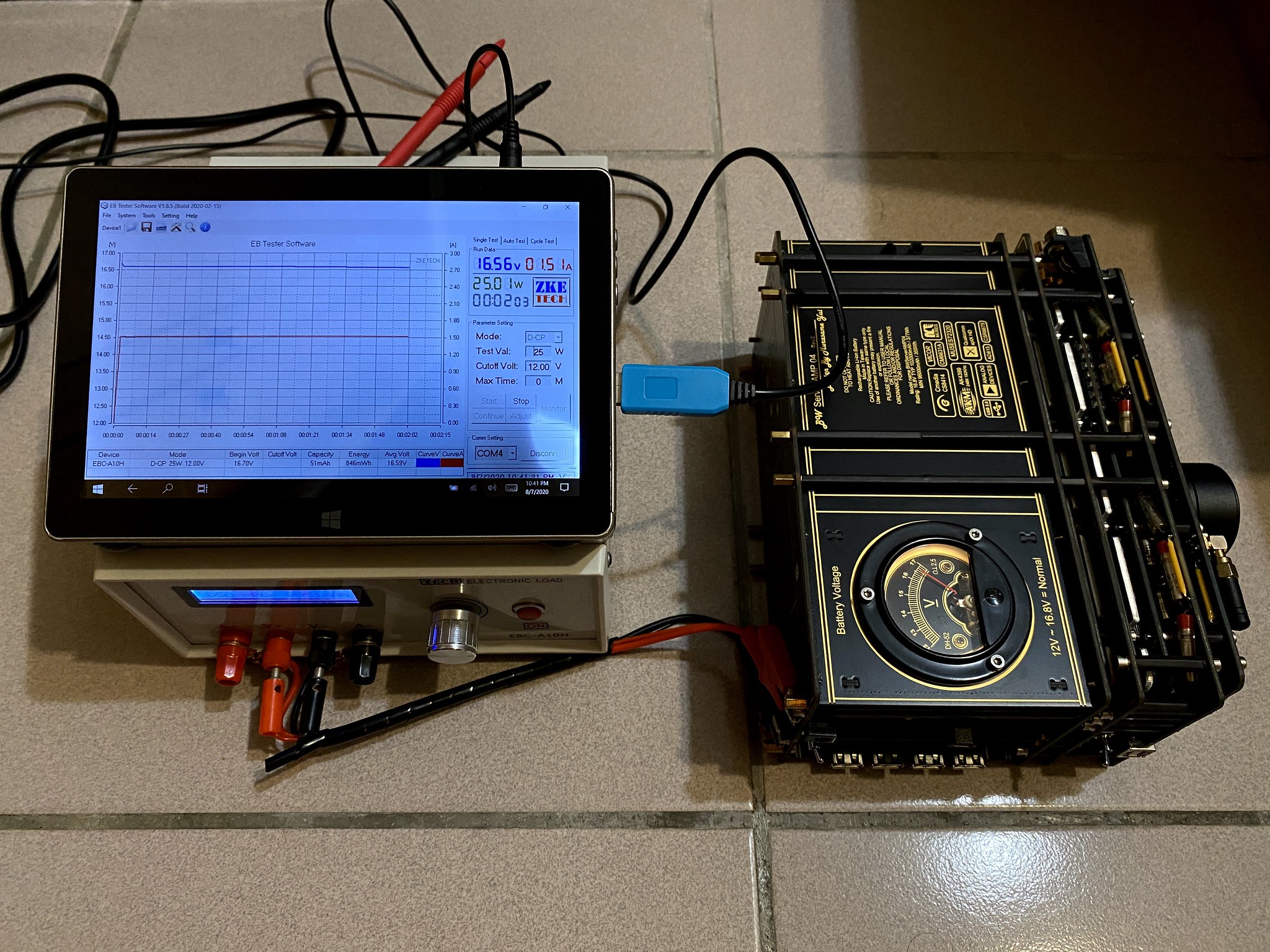
You can setup different discharge current and discharge the cell.
Then the Battery Gauge IC can record this curve in EEPROM
after learning process
It make Battery Gauge IC can Accurately predict battery capacity.
we use Multiple cell in Series together to creat high voltage (for lower operating current)
Lower current mean lower Power loss.
and Multiple cells in parallel together to creat high capacity
But because of the difference in battery internal resistance.
The battery protection / Gauge Ic need to Forecast discharge curve and Computing capacity
So we call this "Charge/discharge process" = "learning process"
And call the "Charge/discharge machine" = " Learning machine"
You can setup different discharge current and discharge the cell.
Then the Battery Gauge IC can record this curve in EEPROM
after learning process
It make Battery Gauge IC can Accurately predict battery capacity.
Last edited:


- Status
- This old topic is closed. If you want to reopen this topic, contact a moderator using the "Report Post" button.
- Home
- Amplifiers
- Headphone Systems
- My DIY BT5.0 headphone amplifier