Hello All,
I'm populating a PCB I bought from the auction site, advertised as:
"5670/ 6N3 + 6080/ 6N5P Stereo Tube Headphone Amplifier Heisang Amp Circuit PCB"
Link here:
5670/ 6N3 + 6080/ 6N5P Stereo Tube Headphone Amplifier Heisang Amp Circuit PCB | eBay
PCB came with the following schematic:
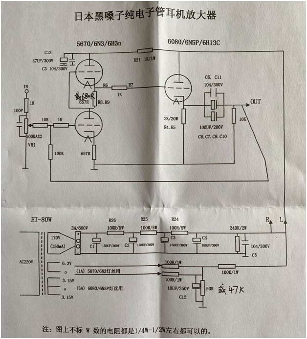
It seems to be an SRPP configuration with a cathode follower.
Filaments are all AC powered.
I 'm particularly puzzled by the 6.3 (1A) supply.
Instead of just feeding the 5670 filaments it keeps going to a couple 100Ω resistors and then it connects to ground and on to the B+ supply via a 100KΩ resistor. I'm no expert here so please help explain what's the purpose of all that (if any)? I plan running DC supply to the heaters but I'm wondering if I need to change something in the process.
Also, any suggestions towards improving this design are very welcome.
It is a cheap little kit but I'm going to give it a try.
I think Douk sells it as Little Bear P7 in a completed form.
Will add some pictures later.
Thank you all for reading.
I'm populating a PCB I bought from the auction site, advertised as:
"5670/ 6N3 + 6080/ 6N5P Stereo Tube Headphone Amplifier Heisang Amp Circuit PCB"
Link here:
5670/ 6N3 + 6080/ 6N5P Stereo Tube Headphone Amplifier Heisang Amp Circuit PCB | eBay
PCB came with the following schematic:
It seems to be an SRPP configuration with a cathode follower.
Filaments are all AC powered.
I 'm particularly puzzled by the 6.3 (1A) supply.
Instead of just feeding the 5670 filaments it keeps going to a couple 100Ω resistors and then it connects to ground and on to the B+ supply via a 100KΩ resistor. I'm no expert here so please help explain what's the purpose of all that (if any)? I plan running DC supply to the heaters but I'm wondering if I need to change something in the process.
Also, any suggestions towards improving this design are very welcome.
It is a cheap little kit but I'm going to give it a try.
I think Douk sells it as Little Bear P7 in a completed form.
Will add some pictures later.
Thank you all for reading.
Attachments

Last edited:
> connects to ground and on to the B+ supply via a 100KΩ resistor.
Tell the whole story. "connects to ground" via a 53kXX 47k resistor, and 100k to +240VDC. Assuming the transformer and heaters are fully insulated, the heater line will sit at +80V (and vibrate +/-3V each side of that).
Why? If there is minor heater-cathode leakage, a DC bias tends to reduce the leakage. In this case, the upper small triode cathode sits at +120V, which is a lot for the heater insulation; the 80V bias reduces the stress.
> connects to ground and on to the B+ supply via a 100KΩ resistor.
Tell the whole story. "connects to ground" via a 53kXX 47k resistor, and 100k to +240VDC. Assuming the transformer and heaters are fully insulated, the heater line will sit at +80V (and vibrate +/-3V each side of that).
Why? If there is minor heater-cathode leakage, a DC bias tends to reduce the leakage. In this case, the upper small triode cathode sits at +120V, which is a lot for the heater insulation; the 80V bias reduces the stress.
Thanks you very much for your help in understanding this.
If I were to power the filaments with DC, should I change anything to thhat part of the circuit?
I was thinking of omitting those couple of 100Ω resistors in order to completely isolate that circuit.
But if I understand correctly, that could put more stress to the heater-cathode isuation and risk leakage?
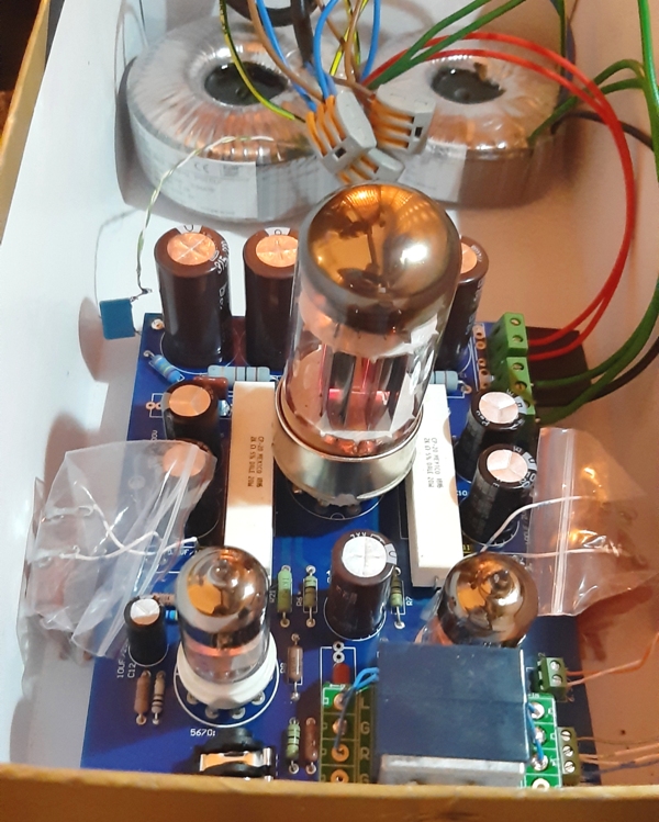
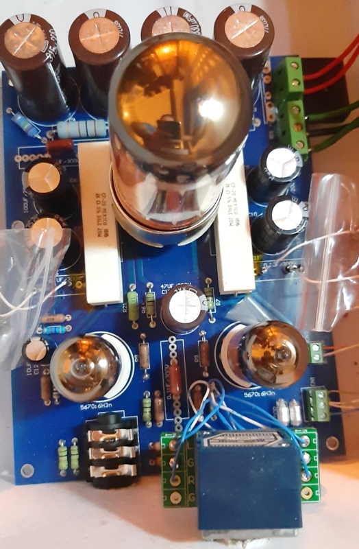
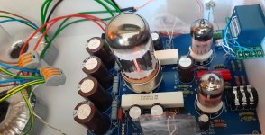
Here are a couple of pictures of the actual PCB.


Last edited:
The 6080 "rings a bell " with me not in audio but old Tektronix oscilloscopes I repaired .
Consistently the 6080,s in them developed heater/cathode shorts ,if I was you I would only buy a high quality US version.
I was able to remove the shorts using a professional CRT rejuvenator which pulsed the current to stop stripping of the cathode surface .
Consistently the 6080,s in them developed heater/cathode shorts ,if I was you I would only buy a high quality US version.
I was able to remove the shorts using a professional CRT rejuvenator which pulsed the current to stop stripping of the cathode surface .
Yeah.The 6080 "rings a bell " with me not in audio but old Tektronix oscilloscopes I repaired .
Reading about that tube, It seems that it was pretty commonly used in several non-audio applications like the one you mention.
What about the 6AS7G one?
Is it less prone to that kind of issue?
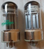
Actually, I got a couple of those 6080. They are the only ones I have for this kit at the moment..
One is a Sylvania (USA) which seems to be pretty common and the other one is a 6080WA by a rebranding company in the name of Chelmer (i think it used to be a UK company). It looks extremely similar to the Sylvania one, so it might actually be a rebranded one.
Both of them are used and the problem is I have no equipment or way to test these.
I haven't put them on the PCB for a test drive yet...
Actually the Sylvania one seems to ring and rattle a bit when I tap it lighlty with my finger. Both do, but the Chelmer seems to do it less.
I might post a video (with sound) so you can tell me your opinions on that.
Last edited:
Yes the 6AS7G by GEC /RCA are a superior make than the stock 6080 never came across the same fault in them .
As a matter of fact in my original valve (tube ) equivalent books the 6AS7/G is vastly superior spec.wise -
Higher anode/plate voltage,
Higher gain ,
Higher current =135MA.
There are also some "SQ" (special quality ) versions--used by governments/military.
Be aware a common fault I found in old audio valves even back in the 60,s was tapping the valves produced a noise at the output when caried out when powered up .
Special rubber cushioned bases existed then to help cure it in ,50,s/60,s
rock and roll groups guitar amplifiers.
An original 6AS7 by either of those two manufacturers might be pricy.
Yes I know Chelmer used to deal with them and yes rebranded now.
Companies House ( UK business check ) state they dissolved in -14 June -2018 (not in liquidation )
previous name-GOIMAGE Ltd.
I have been using this amp for a few hours now and really like it.
I think it is a keeper.
Will write back in a few days, for a more detailed opinion.
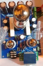
A pic of the two tubes.

I think it is a keeper.
Will write back in a few days, for a more detailed opinion.
I will definitely look around for a 6AS7G.Yes the 6AS7G by GEC /RCA are a superior make than the stock 6080 never came across the same fault in them .
A pic of the two tubes.
Attachments

If you check out the information on the 6080 you will find out why they develop grid/heater/cathode shorts .
The grid/cathode spacing is very close, closer than a normal tube
they get very hot and that causes expansion of the cathode.
Have a look at the superior -6AS7G, its actually designed for single ended audio use -MUCH superior construction .
I have had a 6080 in bits and can vouch for this.
As suspected original RCA/GEC -6AS7G,s are expensive !
6AS7G @ The Valve Museum
I've been using this amplifier with my Sennheiser HD599 pair and I'm positively surprised.
The amp is silent even at the highest volume and the sound I get from it is certainly to my liking.
Comparing it to my previous opamp projects (a Lehmann Black Cube clone with parts from Mouser) this tube amp sounds beautifully.
A more 'organic' and 'full' type of sound that is both smoother and engaging.
This is an OTL design and I wonder If I could do something to further improe the sound. As can be seen in the schematic, each channel's output to the headphones is coupled by two parallel polar aluminuim elecrolytic capacitors (2x100uF, 200VDC) that are also in parallel with a film capacitor of a much smaller value (0.1uF, 300VDC).
In the position for the 0.1uF film capacitor I've used a Cornell Dubilier 3.3uF film capacitor, in parallel with a 560nF Soviet PIO.
The amp sounds nice but I wonder if those two 100uF electrolytics can be ommited completely and be replaced with film capacitors of some smaller value. Maybe a 10uF capacitor alone or in parallel with a smaller value one?
Any feedback on the above would be appreciated greatly!
Thanks for reading!
Attached is a picture of the amplifier at a temporary box.
Attachments
Well you could change the 100uF capacitors for lower value film-caps -IE-polypropylene but you would change the frequency response .
High quality /high voltage polypropylene capacitors are very large and expensive,don't use cheap versions made out of wrapping quality polypropylene.
Try non-polar electrolytic first .
If the FR wasn't involved I would go ahead as I use polypropylene in power amp frequency response feedback as per JLH instead of D,Self high value electrolytic s but the circuits are designed differently .
Well you could change the 100uF capacitors for lower value film-caps -IE-polypropylene but you would change the frequency response .
High quality /high voltage polypropylene capacitors are very large and expensive,don't use cheap versions made out of wrapping quality polypropylene.
Try non-polar electrolytic first.
Duncan,
Thank you for your suggestions.
I was looking for non-polar electrolytics but the voltage rating I need is too high. Usually non-polars go up to 100VDC rating.
Regarding frequency response, will it be affected if I use a total of 20uF capacitance instead of the 200uF electrolytics?
From what I understand the coupling capacitors form a high-pass CR filter with the following 10kΩ resistor to ground.
Right now, with its 200uF capacitor value, the cutoff frequency is at fc = 0.0795 Hz.
So with a 20uF value instead the cut-off frequency would be fc = 0.795 Hz which i think is still quite low.
Do you see any other ways the capacitance value for those coupling caps could affect frequency response by looking at that schematic??
Kind regards,
Nikos.
> what I understand the coupling capacitors form a high-pass CR filter with the following 10kΩ resistor to ground. ... Right now, with its 200uF capacitor value, the cutoff frequency is at fc = 0.0795 Hz.
You are not going to connect headphones to this headphone amp??
I use it with a pair of Sennheiser HD599 (impedance 50Ω).
So, from what I understand the coupling capacitors (C6,7,9,10) form a high-pass CR filter with the following 10kΩ resistor to ground.
A 200uF capacitor value, will result in a cutoff frequency of = 0.0795 Hz.
By looking at the schematic, are there any more ways those coupling caps (C6,7,9,10) affect the frequency response??
I'm no expert.
Still learning.
Thanks in advance.
A 200uF capacitor value, will result in a cutoff frequency of = 0.0795 Hz.
By looking at the schematic, are there any more ways those coupling caps (C6,7,9,10) affect the frequency response??
I'm no expert.
Still learning.
Thanks in advance.
I use it with a pair of Sennheiser HD599 (impedance 50Ω).......10kΩ resistor to ground. A 200uF capacitor value, will result in a cutoff frequency of = 0.0795 Hz....
Wait, I thought you had 50 ohm phones?
The 10k (which you don't listen to), in parallel with 50 Ohm phone (which is what you really want to drive), makes a 49 Ohm total load.
Rule of thumb: 100 Ohms wants 100uFd to get to 20Hz. So 50 Ohms wants 200uFd (and 49 would be 204uFd).
Doing math I get 200uFd with 49 Ohms gives 16.2Hz for -3dB. Which is about 32Hz for -1dB, 64Hz for -0.5dB. OK, not fantastic.
The small-signal response will be flatter lower due to the NFB. But the NBF is small.
If you change to 10uFd then the -3dB point moves up to 320Hz!! Telephone quality bass. NFB may extend small bass toward 100Hz, but large bass is crippled by the too-small capacitor and be both weak and distorted.
There is no sensible alternative to electrolytic caps here.
Attachments
The 10k (which you don't listen to), in parallel with 50 Ohm phone (which is what you really want to drive), makes a 49 Ohm total load.
Rule of thumb: 100 Ohms wants 100uFd to get to 20Hz. So 50 Ohms wants 200uFd (and 49 would be 204uFd).
Doing math I get 200uFd with 49 Ohms gives 16.2Hz for -3dB. Which is about 32Hz for -1dB, 64Hz for -0.5dB. OK, not fantastic.
PRR thank you for your expertise and help!
So, not fantastic at all..
I need good quality and large enough electrolytics.
If you change to 10uFd then the -3dB point moves up to 320Hz!! Telephone quality bass...
..There is no sensible alternative to electrolytic caps here.
Telephone quality bass...

Yeah.
I see there is no way around them.
Problem is I only have a maximum of 17mm diameter space for fitting any.
Your thoughts on these: United Chemicon 470uF 200VDC EKXJ201ELL471ML50 ??
Update on how things progressed so far and how this kit sounds:
After PRR kindly explained that I should calculate high pass with total load in mind (including my cans in the equation) I went all the way and increased capacitance.
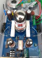
I added more than 6x the original amount (200uF per channel), to the limits my final enclosure would allow (still having the kit in a shoe box for testing).
So, I installed 2x Nichicon KX 680uF (1360uF total per channel) in parallel with:
1uF soviet MBGCh PIO
10uF MBGO (might be replaced with 10uF ERO MKP1813)
0.22uF EPCOS film capacitor (might be replaced with a smaller value KBGO PIO)
Also changed a few resistors. The grid stoppers were replaced with Kayama carbon composition and the feedback resistors with Little Demon carbon films.
Soundwise, I am quite pleased and love the way this kit performs with my 50Ω impedance H599. I will also try them with my HD600 which are higher impedance.
And how it relates to the NFB?
After PRR kindly explained that I should calculate high pass with total load in mind (including my cans in the equation) I went all the way and increased capacitance.
I added more than 6x the original amount (200uF per channel), to the limits my final enclosure would allow (still having the kit in a shoe box for testing).
So, I installed 2x Nichicon KX 680uF (1360uF total per channel) in parallel with:
1uF soviet MBGCh PIO
10uF MBGO (might be replaced with 10uF ERO MKP1813)
0.22uF EPCOS film capacitor (might be replaced with a smaller value KBGO PIO)
Also changed a few resistors. The grid stoppers were replaced with Kayama carbon composition and the feedback resistors with Little Demon carbon films.
Soundwise, I am quite pleased and love the way this kit performs with my 50Ω impedance H599. I will also try them with my HD600 which are higher impedance.
By the way, what is meant by small-signal bass response in contrast to large bass?The small-signal response will be flatter lower due to the NFB. But the NBF is small.
If you change to 10uFd then the -3dB point moves up to 320Hz!! Telephone quality bass. NFB may extend small bass toward 100Hz, but large bass is crippled by the too-small capacitor and be both weak and distorted.
And how it relates to the NFB?
Attachments
Last edited:
- Status
- This old topic is closed. If you want to reopen this topic, contact a moderator using the "Report Post" button.
- Home
- Amplifiers
- Headphone Systems
- Headphone Amp Kit using 5670 + 6080 tubes - suggestions