It's in z.lib.
Are you familiar with LTspice?
Yes I am familiar with LTSpice ;-) Nevertheless you have 2SJ103 in z.lib (with a comment that its a complementary to 2SK246) but no model. The comment is the only occurence of "2SK246" in the file. Anyway, dont´t worry, it does not matter that much.
Yes I am familiar with LTSpice ;-) Nevertheless you have 2SJ103 in z.lib (with a comment that its a complementary to 2SK246) but no model. The comment is the only occurence of "2SK246" in the file. Anyway, dont´t worry, it does not matter that much.
Typo error
There, 2SJ246 Model ( .model 2SJ246.... ) ---> change to (.model 2SK246.... )
About Schematic, LF411/NS......edit the value of U2 from LF411/NS to LF411C as Spice Model ( in z.lib file )
Last edited:
Oh, I get it: in order to keep LTspice from messing with my lib when it's doing its updates, I hide copies all over the place and I must have uploaded an old forgotten one!
My bad, since apologies
While we're on the subject of LF411, have you guys tried both models? Which one is faster?
My bad, since apologies
While we're on the subject of LF411, have you guys tried both models? Which one is faster?
Attachments
Last edited:
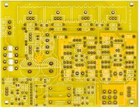
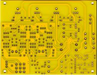
THE HPA: Tweak: power supply: erratum
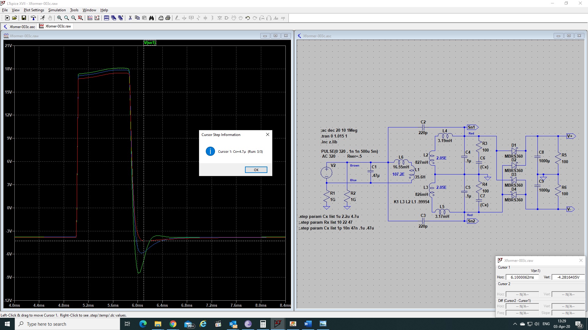
There are BIG mistakes in the values of the transformer (copy/paste from another project). Here's the correct asc - Sorry about that.
Please note the "snubber" values differ significantly from those in the Quasimodo results thread, which average out at about Cx=10n, Cs=150n, Rs=10-100E, with comparable transformers. I think, tentatively, the Quasimodo smacks the secondary, unloaded, whereas I ping the primary with the secondary fully loaded. I'm also building a Quasimodo, and I'll get back to you with findings, if any.
Mark, if you're reading this, would you care to comment?
Attachments
What is your opinion of using Schottky rectifiers? Do you still need the snubber?Thanks.
But if I'm allowed to be rude, I prefer the real thing!
Just a little piece of anecdotal data: the PSU For Chipamps (link) uses Schottky rectifiers AND transformer secondary snubbers AND metal oxide varistors.
That doesn't prove anything of course. It's just one example of one possibility that one person thought would be a good idea. Other people are free to pursue other ideas, naturally.
That doesn't prove anything of course. It's just one example of one possibility that one person thought would be a good idea. Other people are free to pursue other ideas, naturally.
Just a little piece of anecdotal data: the PSU For Chipamps (link) uses Schottky rectifiers AND transformer secondary snubbers AND metal oxide varistors.
That doesn't prove anything of course. It's just one example of one possibility that one person thought would be a good idea. Other people are free to pursue other ideas, naturally.
Not anecdotal: Schottky and snubbers are MANDATORY!!!
Half a century ago, JC told me to hang a 10uF MKP motor cap off the wall outlet, and it actually works.
I don't know about varistors, I've never used them, maybe it's a good time to start. I'm just a bit weary they may be like ferrites (evil).
Yes, this is the Internet free country: when I brought up the subject of ferrites in the CTC thread, all hell broke loose.
By THE guy above.
Many vacuum tube audio enthusiasts say that the combination of very high speed semiconductor diodes such as UF4007, plus a reverse recovery spike filter (a/k/a snubber) across the transformer secondary, improves the sound of their equipment. Not everybody says this, but many do. Have a google for the acronym RRSF to get yourself started. I don't own any vacuum tube gear myself, so I have no fist hand anecdotes to share.
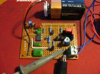
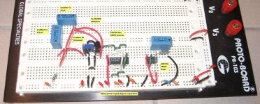
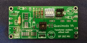
There is a test jig called Quasimodo described here on diyAudio, which simplifies the selection of component values for snubbers.
I never fully understand the concept of a transformer secondary snubber, particularly on solid state amplifier. What is the RFI that induces the ringing? Why the regulator cannot filter it out? Yes, I have read your Linear Audio article. It would be nice to see the ringing also measured at the output of a typical IC regulator PSU.Just a little piece of anecdotal data: the PSU For Chipamps (link) uses Schottky rectifiers AND transformer secondary snubbers AND metal oxide varistors.
That doesn't prove anything of course. It's just one example of one possibility that one person thought would be a good idea. Other people are free to pursue other ideas, naturally.
In the good old days, designer put cap across the rectifier. Now, it was said that it is not necessary for fast diode and some even said that it is harmful.
Thank you for bearing with my naive question.
Last edited:
Install transformer secondary snubbers if you wish; leave them out if you wish. It's your decision. Lots of extremely well loved gear has no snubbers at all. A+ rated, highly collectible, legendary gear from Levinson, Audio Research, Conrad Johnson, Threshold, Krell, Spectral, Apt Holman, Naim, ... the list goes on forever. If those companies can build gear that sounds excellent and has no transformer secondary snubbers, maybe you can too. Certainly you have an "existence proof" that it is possible.
I put snubbers in gear that I design and build because I feel the extra cost is quite small. Even if a with/without listening test finds no meaningful improvement, I don't mind: the price was low. Acceptably low, to me anyway. Others may feel differently and that's perfectly okay with me. Do what you like.
Numerous people have posted their listening impressions, before and after installing transformer snubbers, right on diyAudio. Some heard improvements, some heard no change whatsoever, some heard sonic degradation. I could be mistaken but I think substantially more people reported sonic improvements, than the other two possibilities.
Think for yourself, make up your own mind. Perform experiments yourself if you find measured data reassuring. Listen. Have your audio buddies / spouse / dealer arrange a blind listening test if you want. It's your hobby, enjoy it however you want.
I totally agree, from a slightly different perspective: in the 70's, there were nearly no computers, no SMPS at home, and still, lots of people found their system sounded better late at night. Most of us thought it was because of reduced mains born disturbances.
Nowaday, I have dozens of computers, routers, etc., all with SMPS of course; I must admit I'll so scare I don't even dare to look at the waveform that used to be called "sinusoidal"!
I looked at some commercially available mains filter, even those deemed "audiophile quality", simulated them, and they all ring like bells.
But they do look a lot like snubbers, don't they? Therefore my reasoning is: why not kill 2 birds with 1 snubber? (Birds: the cruelty is not for real).
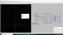
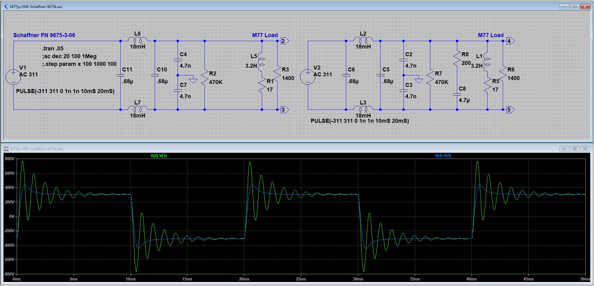
So Mark, that's the meaning of the question I asked a few posts back: I simulate with a pulse hitting the primary, and step the RC values for best damping at the secondary, fully loaded with rectifiers and smoothers. The values I come up with are 10x what people get using your Quasimodo. Any comments?
Nowaday, I have dozens of computers, routers, etc., all with SMPS of course; I must admit I'll so scare I don't even dare to look at the waveform that used to be called "sinusoidal"!
I looked at some commercially available mains filter, even those deemed "audiophile quality", simulated them, and they all ring like bells.
But they do look a lot like snubbers, don't they? Therefore my reasoning is: why not kill 2 birds with 1 snubber? (Birds: the cruelty is not for real).
So Mark, that's the meaning of the question I asked a few posts back: I simulate with a pulse hitting the primary, and step the RC values for best damping at the secondary, fully loaded with rectifiers and smoothers. The values I come up with are 10x what people get using your Quasimodo. Any comments?
Obviously the thing to do is to perform a controlled experiment with a transformer and Quasimodo.
In Part_1 you short the primary wires and also short all secondary wires except one single secondary winding. Connect that winding to Quasimodo, turn it on, and dial up whatever potentiometer setting gives zeta=1 critical damped response. Write the measured value of snub resistance Rs in your laboratory notebook.
In Part_2 you use the exact same setup, with one modification. You connect the output of the RFI filter module to the transformer primary winding(s) exactly as would be used in your 230V/115V application; then, short the INPUTS to the RFI filter module (where the mains would be applied). Turn on Quasimodo a second time, and dial up whatever potentiometer setting gives zeta=1 critical damped response. Write the measured value of snub resistance Rs in your laboratory notebook.
I don't recall ever seeing published data for an experiment like this. Certainly I've never tried it myself. Thus nobody knows whether to expect (Part_1_Rs >> Part_2_Rs) , or to expect (Part_1_Rs ~=~ Part_2_Rs) , or instead (Part_1_Rs << Part_2_Rs) . The trailblazing pioneer who tries this experiment the very first time, gets the thrill of discovering just what actually happens in real hardware.
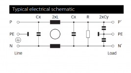
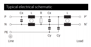
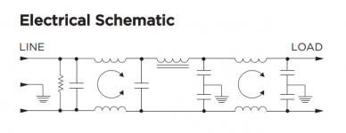
A meticulous and thorough experimenter might divide Part_2 into three pieces (Part_2a, Part_2b, Part_2c) and perform the test with three different RFI filter modules. Perhaps with different max load current ratings {thus different wire gauge in the inductors, thus different inductances}. Perhaps with different numbers of series stages of filtering; one, two, and three stage filters are on the shelf at DigiKey, schematics below. Perhaps with different physical mounting configurations: one a rear panel IEC inlet module with integrated fuses and filter; another, a standalone sealed metal box with screw terminal I/O; etc.
_
In Part_1 you short the primary wires and also short all secondary wires except one single secondary winding. Connect that winding to Quasimodo, turn it on, and dial up whatever potentiometer setting gives zeta=1 critical damped response. Write the measured value of snub resistance Rs in your laboratory notebook.
In Part_2 you use the exact same setup, with one modification. You connect the output of the RFI filter module to the transformer primary winding(s) exactly as would be used in your 230V/115V application; then, short the INPUTS to the RFI filter module (where the mains would be applied). Turn on Quasimodo a second time, and dial up whatever potentiometer setting gives zeta=1 critical damped response. Write the measured value of snub resistance Rs in your laboratory notebook.
I don't recall ever seeing published data for an experiment like this. Certainly I've never tried it myself. Thus nobody knows whether to expect (Part_1_Rs >> Part_2_Rs) , or to expect (Part_1_Rs ~=~ Part_2_Rs) , or instead (Part_1_Rs << Part_2_Rs) . The trailblazing pioneer who tries this experiment the very first time, gets the thrill of discovering just what actually happens in real hardware.
A meticulous and thorough experimenter might divide Part_2 into three pieces (Part_2a, Part_2b, Part_2c) and perform the test with three different RFI filter modules. Perhaps with different max load current ratings {thus different wire gauge in the inductors, thus different inductances}. Perhaps with different numbers of series stages of filtering; one, two, and three stage filters are on the shelf at DigiKey, schematics below. Perhaps with different physical mounting configurations: one a rear panel IEC inlet module with integrated fuses and filter; another, a standalone sealed metal box with screw terminal I/O; etc.
_
Attachments
Actually, my thinking is not to use a RFI filter at all, maybe just a Cx instead, and rely solely on the snubber at the secondary to deal with the RFI at the primary.
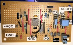
LTspice says it's possible, but I don't have any means to verify it yet, my Quasimodo is still missing some parts. Maybe by the end of the month, as China is still in recovery.
LTspice says it's possible, but I don't have any means to verify it yet, my Quasimodo is still missing some parts. Maybe by the end of the month, as China is still in recovery.
Last edited:
THE HPA: schematic, revision "c"
No major change:
No major change:
- Applied Mooly's Magic for a much cleaner FFT
- Cleaned up some components references
- Cleaned up some components values
Attachments
Seriously way off topic here, yes, power supply includes A/C to DC conversion...
I’ve had the E4 running for the last couple years as a preamp until a recent esd event took out the input fets. Will try something different and then decide whether to fix it or move on.
I really wish the E5 were still available, is a much better sounding amp.
Original Weilaing headphone amp thread here;
My E5 Class A hifi headphone amp
It is interesting that you found the E5 to be better sounding than the E4. Does that mean that the Marantz HDAM input topology is better than the JC2 dual differential jFET? They have different driver stage too. Is it the driver stage that makes the major difference in sound?Seriously way off topic here, yes, power supply includes A/C to DC conversion...
I’ve had the E4 running for the last couple years as a preamp until a recent esd event took out the input fets. Will try something different and then decide whether to fix it or move on.
I really wish the E5 were still available, is a much better sounding amp.
Original Weilaing headphone amp thread here;
My E5 Class A hifi headphone amp
I have a JC2 in a line preamp for awhile, it sounds very good to me. But I have never heard the E4. I expect the E4 to sound excellent too. My E19 headphone amp board is a practical copy of the E5.
- Home
- Amplifiers
- Headphone Systems
- The JC2-HPA Headphone Amplifier