It looks like we only have the fuel gauge circuit left to debug now that you have reported that the battery is charged to 4.2v. That’s a full charge I believe. So it looks like the NTC is mandatory then - it may actually allow the charge to go faster as it will use an algorithm for temperature vs current for rapid charge.
The testing of the prototype continues in IAIMH’s lab. We are making great progress and last thing is trying to sort out the fuel gauge. When a momentary button is pushed, the battery levels are compared against a reference voltage determined by resistive dividers. The comparator is an open collector type and pulls current to light up an LED when the battery voltage drops below its reference voltage.
Attachments
Last edited:
X - I'm excited that the battery charging / babysitter is working properly. Apologies for not catching that the thermistor was required earlier. I got lost in that spec sheet. More to learn.
After some thought, I may try putting a USB-C on the other board. I'll need to get confident enough with the SMD soldering using the board heater. Being able to plug the Hakuin into one of my battery "bricks" while on long plane rides would be excellent! With the PCA, I just swap out the batteries. Having an option to keep it running using external battery power would work very well in my use case.
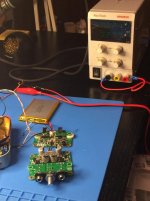
Here's a pic of my exceptional testing set up. No laughing at the 10k resistor hanging off
I'm monitoring the battery / indicators for a full charge and/or when the circuit does not draw any more current. This particular battery (as you pointed out) has its own protection circuit, so it has stayed at room temperature for the entire period. Current draw started off at ~1A4. Now it's around 0A28. Per the spec sheet, the baby sitter has a constant current and a constant voltage charging sequence (if I understood it properly). We're in the constant voltage part of the sequence at this point... I think.

Edited to add - Jinx! You owe me a Coke.
After some thought, I may try putting a USB-C on the other board. I'll need to get confident enough with the SMD soldering using the board heater. Being able to plug the Hakuin into one of my battery "bricks" while on long plane rides would be excellent! With the PCA, I just swap out the batteries. Having an option to keep it running using external battery power would work very well in my use case.
Here's a pic of my exceptional testing set up. No laughing at the 10k resistor hanging off
I'm monitoring the battery / indicators for a full charge and/or when the circuit does not draw any more current. This particular battery (as you pointed out) has its own protection circuit, so it has stayed at room temperature for the entire period. Current draw started off at ~1A4. Now it's around 0A28. Per the spec sheet, the baby sitter has a constant current and a constant voltage charging sequence (if I understood it properly). We're in the constant voltage part of the sequence at this point... I think.
Edited to add - Jinx! You owe me a Coke.
We have a bit more progress. After some measurements and X's brain power, he determined that the operating point for the "brain" of the fuel gauge was not set properly and would not turn on. A quick resistance swap, and he said... Let there be light... and there was light.

A tweak of the operating points to fine tune, and perhaps a change in resistances to lower the brightness of the greens and raise the yellows a bit... and I may want a red... and this prototype will need a case / tin to live in.
Let there be Rock!
Edited to add - X, I somehow missed your last post until this posted and refreshed. Thank you so much for the offer on the Yarra boards. Absolutely thrilled to try them out.
Hi IAIMH,
Excellent progress. We are almost there. Overall, the circuitry and layout was good. We are catching some errors on resistor setpoints for the fuel gauge. Also the setpoint for the BJT collector needs to be adjusted to 12v, currently 14v. But overall, a very good first prototype and not bad at all for how complex this system was.
Thanks for being the verification builder!
Jhofland is calculating what all the resistor setpoints need to be for the fuel gauge function to work properly. It appears that the voltage drop across one of the LEDs was not properly accounted for in the design. Should be doable though, but that will wrap up all of the prototype issues and we can get the next version for production to be close to perfect. I still need to set the operating point for the BJT collector to be near 12v while maintaining a suitably high enough bias current and keep the harmonic profile split between H2 and H3 at a good ratio.
Excellent news! Once we've got all the new values, I'll get started on PSU#2. I'm itching to use my new PCB heater on something other than practice boards
Thanks again for sharing your knowledge. I've learned quite a bit.
Now, I've started down the rabbit hole on some of the AKSA-inspired circuits. More to learn...
Thanks again for sharing your knowledge. I've learned quite a bit.
Now, I've started down the rabbit hole on some of the AKSA-inspired circuits. More to learn...
I just replaced R207/R208 with 2k2 (vs 2k7). Bias current is now 60mA and voltage at the collector of the BJT is 11.90v - perfect. Putting this value in the LTsoice sim shows a good agreement. Predicted THD for 1Vpp into 250ohms is 0.046% and H2 is 36x higher than H3. I listened to a few tracks and it sounds superb.
I am testing the Hakuin with my OB-1 headphones (55ohm), and I must say it sounds abssolutely wonderful. One of the best headphone amps out there at any size or price. And I have listened to a lot of headphone amps. It seems that having just 2 transistors is perfectly suitable for headphone amp purposes. It has no problem driving the OB-1's to clean and uncomfortably loud levels. The bass is very clean and powerful - distinctly so. The sonic signature is natural and engaging without any sign of harshenss or fatigue. Listening to Samba Triste by Stan Getz at the moment.

Attachments
IAIMH, Thanks for taking the time to share your listening impressions. It sounds like Hakuin has the PCA magic and then some. I tried a great many coupling caps in my PCA builds, and while they all changed the timbral texture to a degree, the fundamental character of X's circuit, to my ears, is exactly what you reported. That overall "ease of presentation" you described. Effortless power. I'm glad Hakuin is building upon this foundation.
I will be offering the Hakuin topology as a preamp module for the Yarra preamp. There board will be all through hole except for the 2SK209BL and DZT5401. However, if you want, 2SK170BL and 2S1837 can be used for an all through hole design.
More info here:
The YARRA Preamplifier/HPA for Melbourne DB Group Buy

More info here:
The YARRA Preamplifier/HPA for Melbourne DB Group Buy
Someone on the "Walnut and Zishan Enthusiasts (WaZe)" Facebook group, just posted a link to the Aune B1s portable amp (fully discrete transistor circuit, with Class-A output transistor biasing).
Its output is spec'd at:
42mW into 600Ω
74mW into 32Ω
84mW into 300Ω
The output current can be "switched", and the battery life is listed as 10 hours with output current at 20mA, and 5 hours at 40mA.
The B1s sells for $230 at Penon Audio.
Have you heard the Aune B1 or B1s - and can you compare the sound / performance / cost with the Hakuin?
Hi Dave,
I have not heard of the B1 by Penon until now. I see it has 10 small SOT23 actives and two TO220 DPAK outputs for 12 total transistors. This looks like a conventional LTP with constant current sources and push pull output biased to be high current for Class A operation. Since it has very low 0.0002% THD I suspect it uses a lot of feedback. Without hearing it, here is what I suspect the differences based on topology.
So the differences are:
1. LTP input stage cancels even order distortion and magnifying odd orders. Will sound bright and sharp. Possibly fatiguing.
2. Lots of actives will increase background noise level vs 2 transistors. Blacks won’t be as black.
3. Ultra low distortion requires high levels of negative feedback. This alters the phase relationships ever so slightly that it doesn’t sound as engaging and soundstage and imaging will be not as good as a zero global feedback amp.
4. Push pull output stage will sound very dynamic and punchy but cancels even order distortion leaving higher levels of odd order H3, H4, H7 etc. this may sound fatiguing over time. Whereas a single ended (SE) Class A naturally had dominant even order and higher second order and a monotonically decreasing progression of higher orders which sounds natural and pleasing and warmer. Not fatiguing.
Of course, this is all my conjecture based on the top photo of the components. They are using MELF resistors and that’s very nice.
It looks like an interesting amp but a totally different animal than the Hakuin which asks you: “what is the sound of two transistors clapping?” versus the sound of 12 transistors in a recursive high negative feedback loop.
You have my PCA amp - you were one of the first customers to buy one. How does the sound compare to your other ultra low distortion high transistor count amps? Which one sounds the most pleasing and natural? Hakuin will be similar to PCA but with more resolution of details and attack is sharper, bass is more crisp.
Last edited:
Just an update. We got the new fuel gauge circuit figured out wit Jhofland’s expert help. JPS64 has given me a diagram to facilitate cutting traces and adding a LM431 voltage reference via deadbug. I received the new resistors and parts from Mouser the other day so hopefully will have time to make the full smart charger PSU this weekend.
I think member Itsallinmyhead will be doing a similar thing very soon as well. We were both pulled away by other pressing projects. But will be returning soon. This amp sounds amazing with the new ESS 422H hybrid AMT headphones. If you don’t have one yet, get one! They are that good!
ESS 422H AMT Hybrid Headphones
(I don’t get anything for plugging this product from ESS - just want others to experience the insane sound quality and resolution they can afford.
Good to see progress is being made and that you tracked the fuel gauge problem down.
I've been listening to this circuit for several weeks now and am really enjoying the sound.
I thought that the slightly higher distortion levels with lower impedance headphones would make the amp sound not as good as others I've built, but that's not the case. This circuit sounds quite warm and detailed, with a touch of softness in the lower frequencies. Dead silent at idle and nice, low distortion when used with higher impedance headphones.
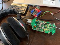
This is on my desk right now:

I can't share the exact details just yet, but i'm currently trialling J113 paired with MJE253G, running hotter at 75mA bias, and it sounds fantastic.
I just tried my old-school Yamaha HP50S Orthodynamic (150ohms) and despite the poor LF response of those headphones (not the circuit), the overall experience was excellent, so I'd love to try out some of those hybrid ESS! The circuit performed perfectly, even with having a decent workout from the demanding Orthodynamics!
I'm looking forward to seeing the release of the Pocket and Melbourne versions because I've heard how good this circuit can sound and know what the build quality is going to be like! We're definitely in for another treat!
I've been listening to this circuit for several weeks now and am really enjoying the sound.
I thought that the slightly higher distortion levels with lower impedance headphones would make the amp sound not as good as others I've built, but that's not the case. This circuit sounds quite warm and detailed, with a touch of softness in the lower frequencies. Dead silent at idle and nice, low distortion when used with higher impedance headphones.
This is on my desk right now:
I can't share the exact details just yet, but i'm currently trialling J113 paired with MJE253G, running hotter at 75mA bias, and it sounds fantastic.
I just tried my old-school Yamaha HP50S Orthodynamic (150ohms) and despite the poor LF response of those headphones (not the circuit), the overall experience was excellent, so I'd love to try out some of those hybrid ESS! The circuit performed perfectly, even with having a decent workout from the demanding Orthodynamics!
I'm looking forward to seeing the release of the Pocket and Melbourne versions because I've heard how good this circuit can sound and know what the build quality is going to be like! We're definitely in for another treat!
Attachments
Last edited:
Nice work Avtech! I guess you couldn’t wait for the official board before testing the topology for sound quality. Glad it sounds good and is working. The component choice on this amp does make a difference in sound quality. I am not sure the J113 is the best JFET for this application. Either BF862, 2SK209BL or 2SK170BL would have been the ideal choices. Each one requires an different resistor setpoint for proper operation relative to the Idss and above midpoint voltage at the output cap. Did you simulate the circuit with the J113 and MJE transistor get the correct setpoints? The MJE you selected is interesting - but the ideal one to hear what the amp can sound like, is the venerable 2SA1837. Out of production but I have new ones (genuine Mouser old stock) I can provide with the boards. There are lots of threads for 2SK170BLs so those are not that hard to get. But 2SK209BL sound just as good I think.
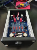
Also, noticed you have no heat sinking on the outputs?
Nice looking build though.

Btw, a Hakuin Yarra format daughterboard is being manufactured and so folks can start enjoying on their Yarra or M2X amp.
JPS64 is also working on a Yarra Mini motherboard for use as a compact HPA.
Also, noticed you have no heat sinking on the outputs?
Nice looking build though.
Btw, a Hakuin Yarra format daughterboard is being manufactured and so folks can start enjoying on their Yarra or M2X amp.
JPS64 is also working on a Yarra Mini motherboard for use as a compact HPA.
Last edited:
The circuit looked interesting so I wanted to give it a try. I couldn't wait to agree with you on the SQ of this one!
I have tried the 2SK170 and they sound a little better to me but I wanted to try in-production components that are easy to obtain. J113 is what NP uses in the Korg B1 as a substitute for the 170 so I figured they would be a good choice. Neither the J113 or the MJE are obsolete, so it makes it easier (and cheaper) for me to obtain.
I've run many simulations and set the MJE to around 11v to get nearly symmetrical clipping (a little above midway does sound better). The JFet was pretty happy with the same set points in the Sim and it doesn't distort in use. The circuit has been pretty tolerant to me playing around with it.
The MJE are running reasonably cool. They are designed for higher currents, so they are well within SOAR at their operating points. I did position them on the board for heatsinks, just didn't install them.
The output resistors are only in series (not series/parallel) due to board space, so they are sat around 400mW each and nice and warm! But class-a is meant to double as a room heater
I'm waiting on some SMD - THT adapters (currently stuck in the factory) so that I can try out the silicon you chose to see the difference. Until then, I have some BD140 on hand that I might give a run...
Cool. Is that an LM317 regulator for the 18v PSU?
You really need to get the ESS 422H headphones. They are the best I have heard of all my cans thus far. The sensitivity is like a BA IEM so only takes about 300mVpp output for deafening levels. Hence, very low current requirement from the amp.
The 422’s paired with the Hakuin, is in my opinion, one of the best sounding rigs at any price.
I've put a LM7818CT in there at the moment as I am using a 24v PSU. There is a CRC filter stage before that also. The LM7817CT is specc'd at minimum 62dB PSRR and the ripple should already be fairly low from the output of the CRC.
I want to run some measurements on the plain LM regulator before I swap it over for an LDO ultra-low noise regulator. I left space to accomodate this with it's heatsink and curious to see if it makes a difference.
I've got enough options to just use bridging links if I don't want to include a particular stage, or breakout to a separate board if needed.
I like to experiment with the power supply configurations to see how little I can get away with and still maintain quality.
Even driving the Yamaha HP50s, I was only at 22% volume for the upper limit of what I find comfortable and that's with just 93 dB/mW. This circuit is quite capable!
I saw some on the Amazon AU site but they wanted $930AUD which is a bit rich! I see they can be shipped direct from ESS for about $350AUD.. so it's definitely tempting!