After several years and hundreds of units of the popular Pocket Class A (PCA) headphone amplifier having been released into the wild, I thought it was time for a second version. This time though, I will name it after the 17th century Zen master Hakuin Ekaku, who popularized the koan "What is the sound of one hand [clapping]?" I think minimalism in audio can produce some of the best amps. It is this minimalist approach to the original two field effect transistors that produced a wonderful sounding amp that was unanimously liked in reviews. Now we will have an amp that uses one JFET and one BJT, together as a complementary feedback pair (CFP). Although, I love the sound of the BF862, it has been harder to find due to EOL issues. To keep things accessible, I will be using the readily available 2SK209 for the JFET and a compact DZT5401 PNP BJT in SOT223 format for good thermal dissipation. The Hakuin’s CFP topology and initial circuit was developed by Hugh Dean (AKSA), and is in my opinion, one of the best sounding headphone amps you can hear. Time will tell though as folks listen to this amp.
So we know what the sound of two FETs is, now, what is the sound of one?
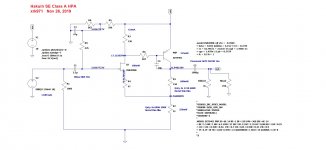
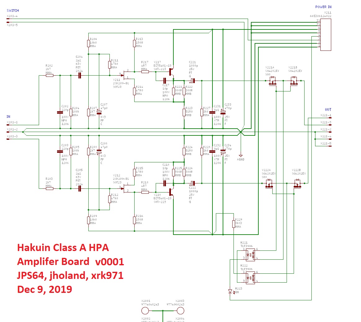
Here is the LTSpice schematic:
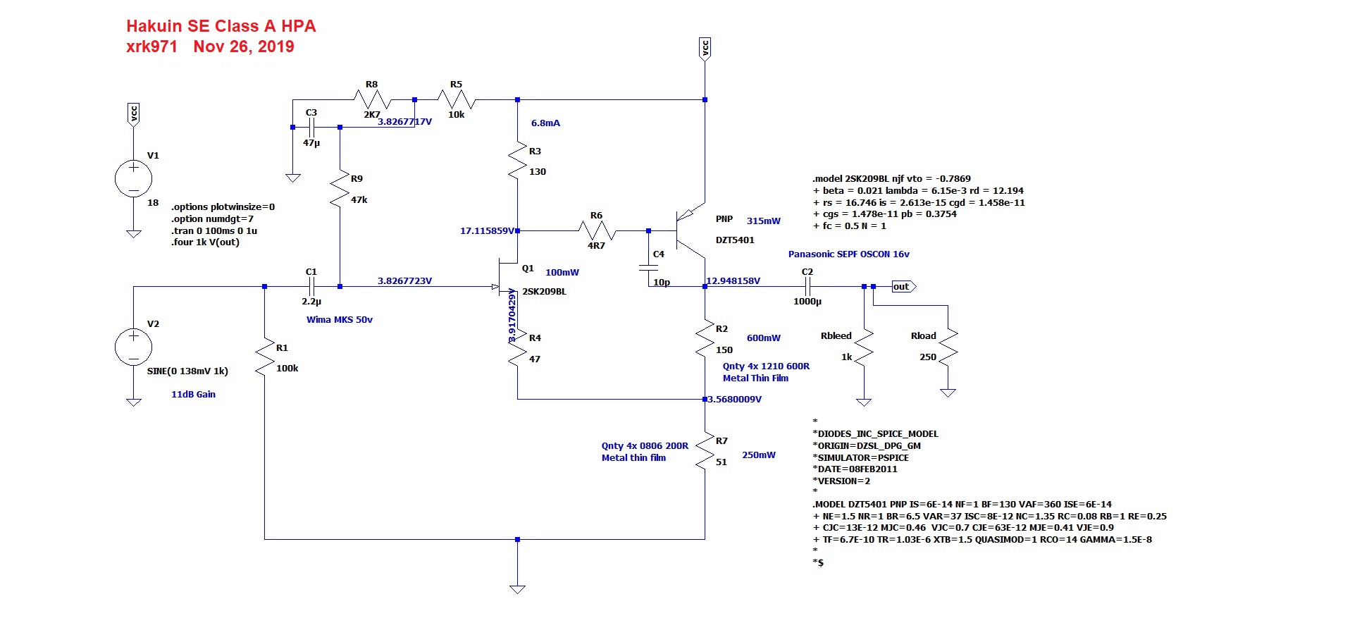
The predicted harmonic profile is dominant 2nd order, with a small amount of third order distortion, and not much else. Driving 250 ohm headphones, this amp will produce a very musical, immediate presence, and with superb resolution and dynamics. I have tested it out with a BF862 and 2SA1837. Both un-obtanium, so now redoing it with easy to find parts. The overall THD will be a bit less than the previous JFET-MOSFET version.
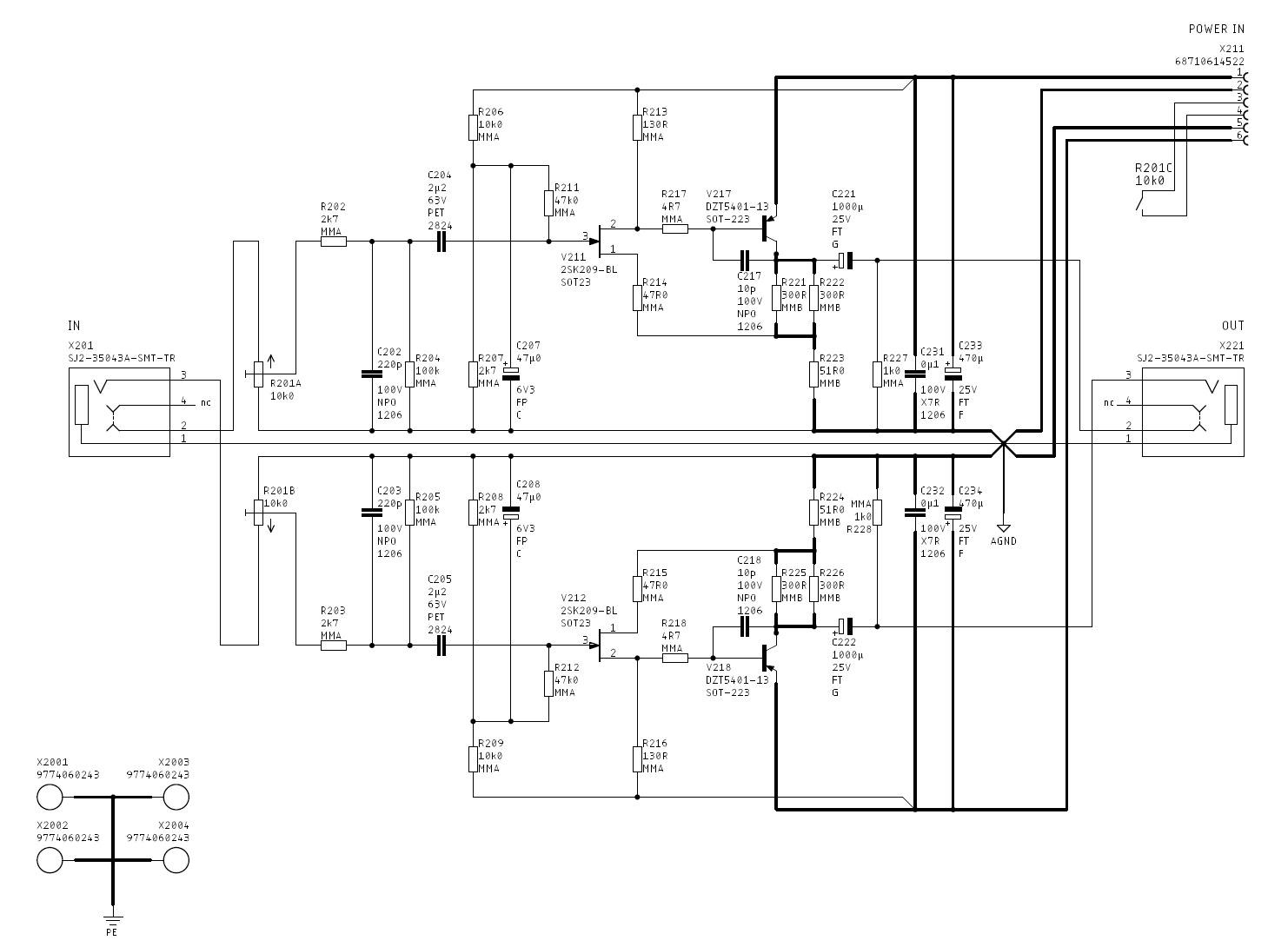
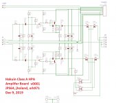
With the help of JPS64, who put into a compact PCB, the schematic looks like this, now with some RFI filtering and in stereo:
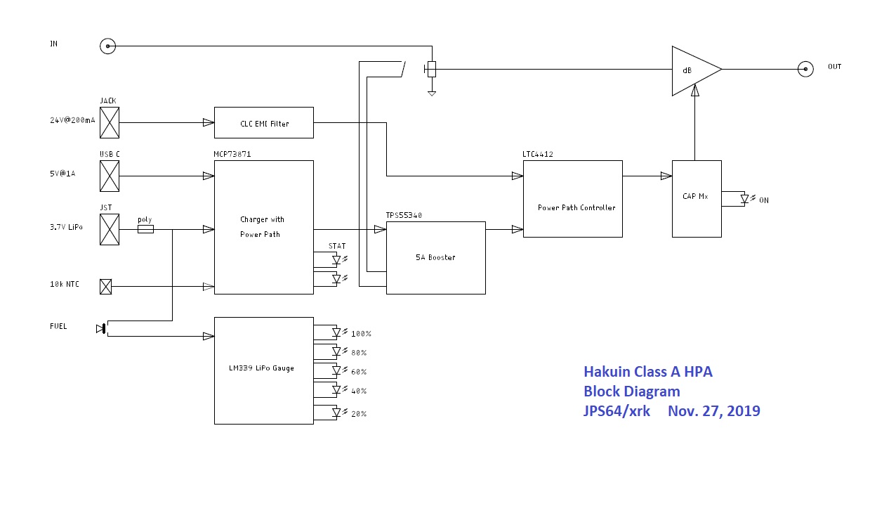
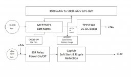
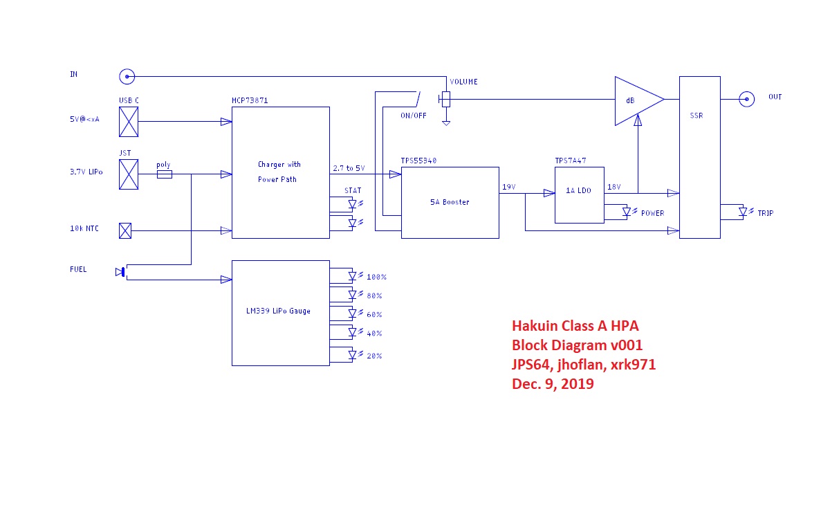
This will still be a pocket amp, but this time, we are making our own power system with LiPo batteries, a battery management system, DC-DC boost converter, SSR for power on/off, capacitance multiplier for soft ramp up to avoid pops and reduce noise, and a battery gauge meter with LEDs. Here is the block diagram (Edit - updated 11/27/19):
Here is a calligraphy painting by Hakuin to get us into the right mindset of simplicity and the beauty of nature:

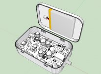
Maybe the amp will look like this, still fits in a simple Altoids mint tin - same as the orginal PCA, but with so much more value added features:

I would like to thank Hugh Dean and JPS64 for their help in this amp collaboration. This project really is the realization of the goal of a pure, natural sound, from a elegantly simple two transistor amp, but wrapped up in a state of the art package with the latest smart battery management and ultra quiet power supply.
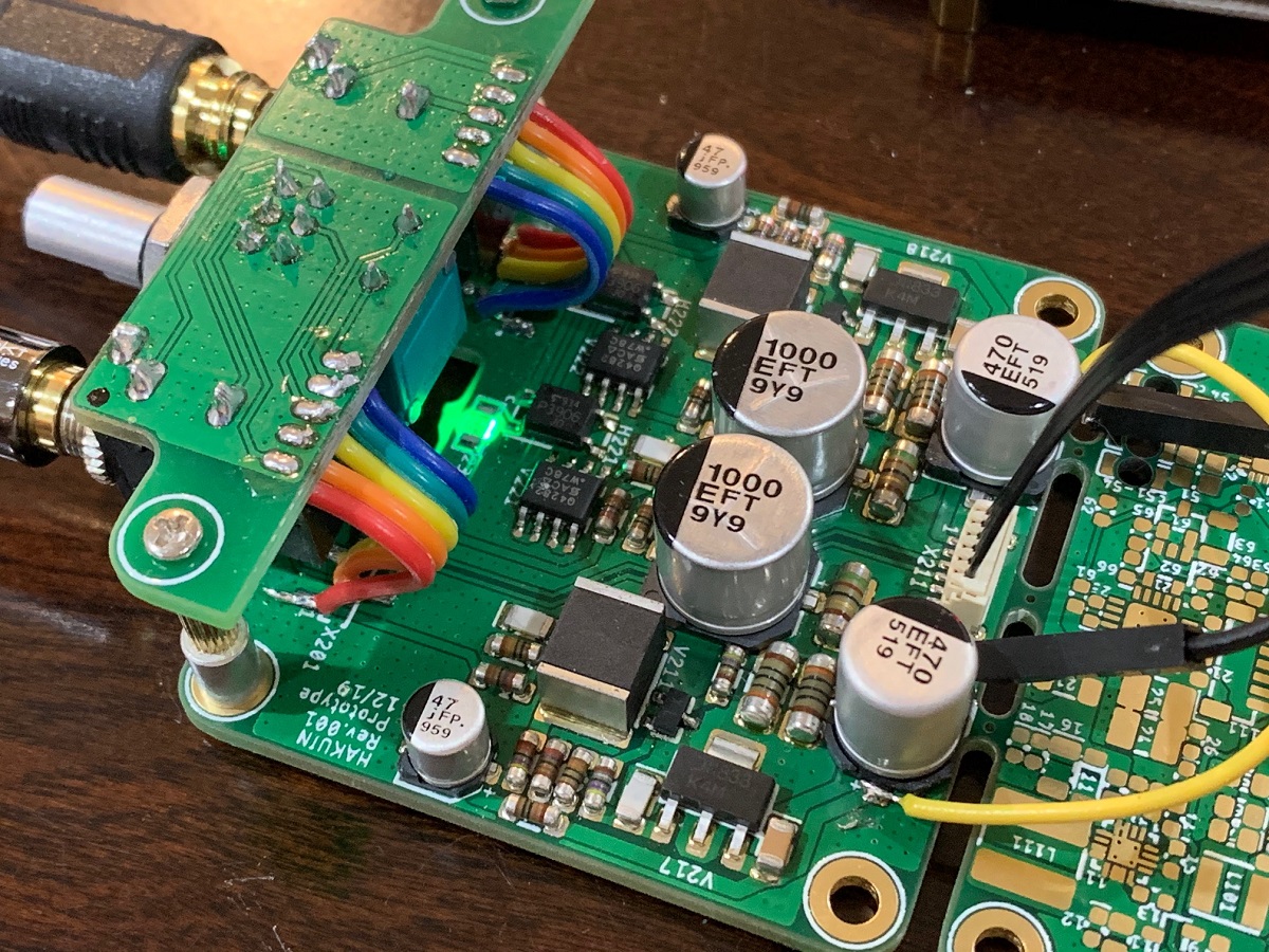
Edit Jan. 14: the prototype amp is alive and songs beautifully. IAIMH helped me with the verification build and got first sound on Jan 10 and for it working on both channels on the 12th. The battery charger and DC step up now also appears to be working.
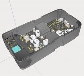
Here is the amp section on mine under first sound testing:
So we know what the sound of two FETs is, now, what is the sound of one?
Here is the LTSpice schematic:
The predicted harmonic profile is dominant 2nd order, with a small amount of third order distortion, and not much else. Driving 250 ohm headphones, this amp will produce a very musical, immediate presence, and with superb resolution and dynamics. I have tested it out with a BF862 and 2SA1837. Both un-obtanium, so now redoing it with easy to find parts. The overall THD will be a bit less than the previous JFET-MOSFET version.
With the help of JPS64, who put into a compact PCB, the schematic looks like this, now with some RFI filtering and in stereo:
This will still be a pocket amp, but this time, we are making our own power system with LiPo batteries, a battery management system, DC-DC boost converter, SSR for power on/off, capacitance multiplier for soft ramp up to avoid pops and reduce noise, and a battery gauge meter with LEDs. Here is the block diagram (Edit - updated 11/27/19):
Here is a calligraphy painting by Hakuin to get us into the right mindset of simplicity and the beauty of nature:
Maybe the amp will look like this, still fits in a simple Altoids mint tin - same as the orginal PCA, but with so much more value added features:
I would like to thank Hugh Dean and JPS64 for their help in this amp collaboration. This project really is the realization of the goal of a pure, natural sound, from a elegantly simple two transistor amp, but wrapped up in a state of the art package with the latest smart battery management and ultra quiet power supply.
Edit Jan. 14: the prototype amp is alive and songs beautifully. IAIMH helped me with the verification build and got first sound on Jan 10 and for it working on both channels on the 12th. The battery charger and DC step up now also appears to be working.
Here is the amp section on mine under first sound testing:
Attachments


Last edited:
If we make a continuous carbon fiber filament 3D printed case using MarkForged Onyx nylon, we can have a case that is stronger than aluminum.
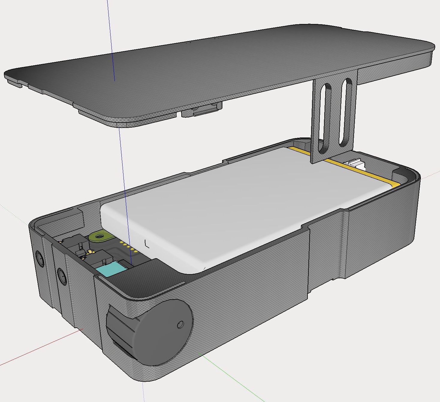
The material may have better thermal transfer too for the bottom heatsink.
The material may have better thermal transfer too for the bottom heatsink.
Attachments

After some discussions with the team, we are going to change some items in the power supply section. Probably go with a TPS7A4xxx 4uV rms LDO instead of a cap Mx to clean up the power supply and preserve battery life. Also switch to a SSR for swithching on/off the output to prevent turn-on thump. No need for DC protection given that it is AC coupled output. Jhofland has been helping us with the finer points of the electrical design. This will be a very nice headphone amp with many state-of-the-art features.
An update for folks following this thread. Jhofland and JPS64 have been working very hard to come up with a user friendly and battery life extending design.
The design of the power system is a long and complicated process. We are weighing pros and cons with different DC-DC boost methods, switching LiPo vs linear charge controllers, and SSR MOSFETs for a main power on/off “soft switch”. It’s going to be a nice well engineered unit though.
The design of the power system is a long and complicated process. We are weighing pros and cons with different DC-DC boost methods, switching LiPo vs linear charge controllers, and SSR MOSFETs for a main power on/off “soft switch”. It’s going to be a nice well engineered unit though.
Well, the power supply is the trickiest part of a portable Amp or DAP - especially if you want it to recharge from a USB charger.
Looking forward to hearing how the final design sounds, and how much it costs.
And, you know me - I'd like to see a Balanced version, or at least a 2.5mm TRRS output jack connected to the Single-Ended amp (so I don't have to use a 3.5mm TRS Plug -> 2.5mm TRRS Jack adapter for my Balanced cables).
Looking forward to hearing how the final design sounds, and how much it costs.
And, you know me - I'd like to see a Balanced version, or at least a 2.5mm TRRS output jack connected to the Single-Ended amp (so I don't have to use a 3.5mm TRS Plug -> 2.5mm TRRS Jack adapter for my Balanced cables).
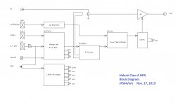
We have the updated design now with several enhancements: a MOSFET based solid state soft power switch triggered by the mechanical switch on the volume knob. This prevents arcing and wear associated with a mechanical switch. We eliminated the cap multiplier as a means to prevent turn on thump (it was too wasteful of power) and we now have a pair of opto-isolator controlled SSR's at the output of the amp. These will not close until a sufficient delay has elapsed to prevent turn on thump (3-5 seconds). This type of back-to-back low RDson MOSFETs have been shown to not contribute anything to the audio signal. An ultralow noise (4uV) TPS7A4xxx LDO is now being used to provide clean power to the audio amp at a nice constant voltage to prevent change in sonic signature with battery power. A switching LiPo battery management system/charger is also being used along with a DC-DC boost to provide the 19v to the LDO. Here is the revised block diagram:
Here is the revised audio amp section - you can see the opto-controlled SSR's for the output:
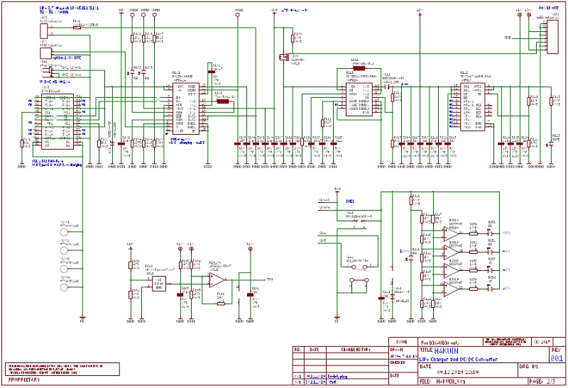
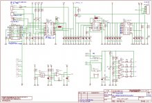
Here is the (blurred) schematic of the power supply section just to give an idea of the complexity of the power suppy section:
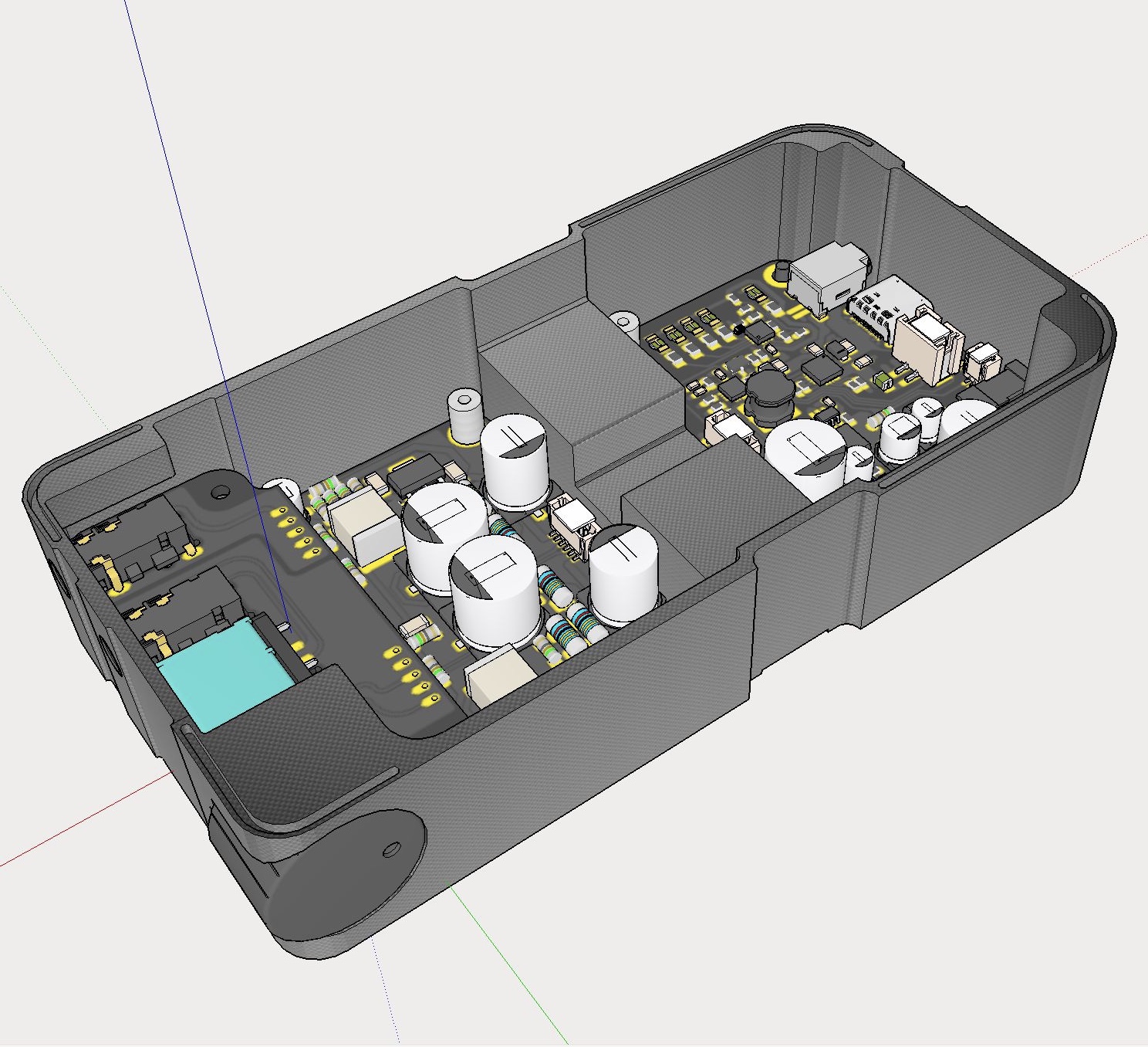
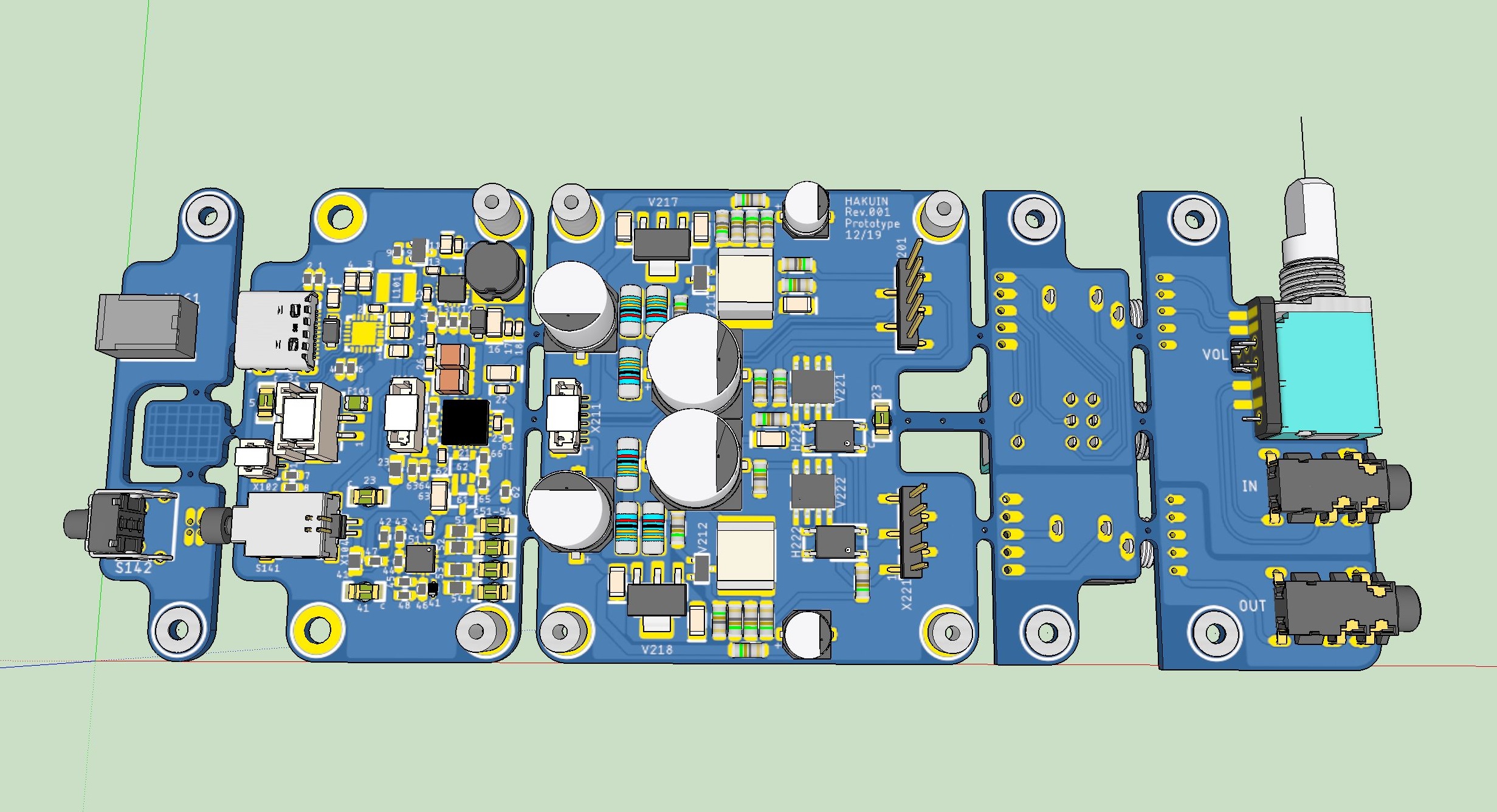
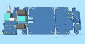
Here is a 3d render of the assembled PCB:
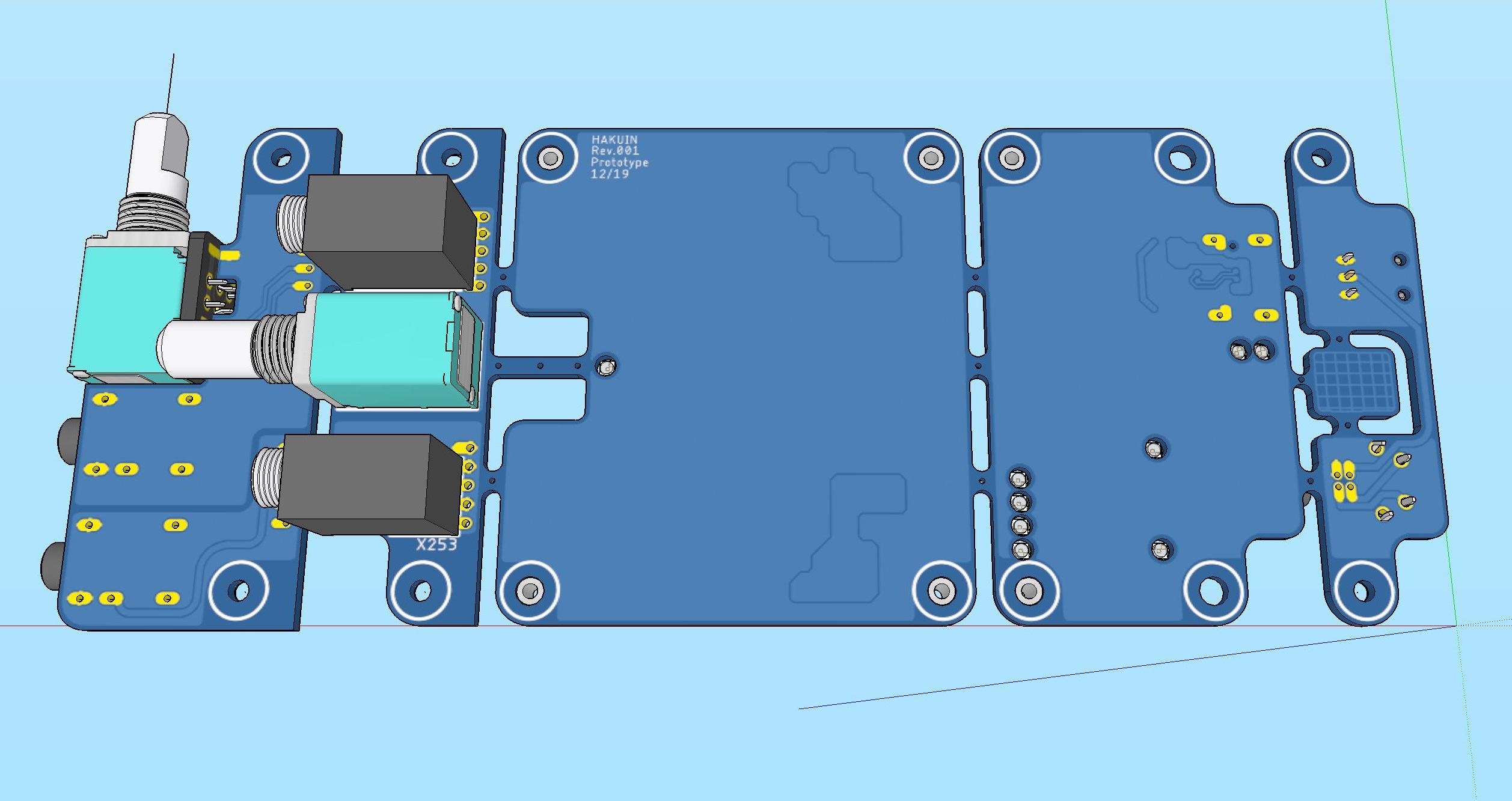
Here is a render of the bottom side:
Here is the revised audio amp section - you can see the opto-controlled SSR's for the output:
Here is the (blurred) schematic of the power supply section just to give an idea of the complexity of the power suppy section:
Here is a 3d render of the assembled PCB:
Here is a render of the bottom side:
Attachments


Last edited:
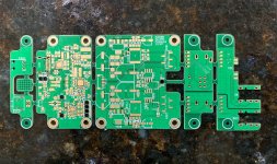
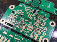
The prototype PCBs for the Hakuin arrived today. They turned out real nice. This will be a fun build! (maybe one time).
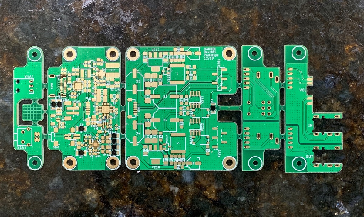
Power management system and DC-DC step up plus regulator:
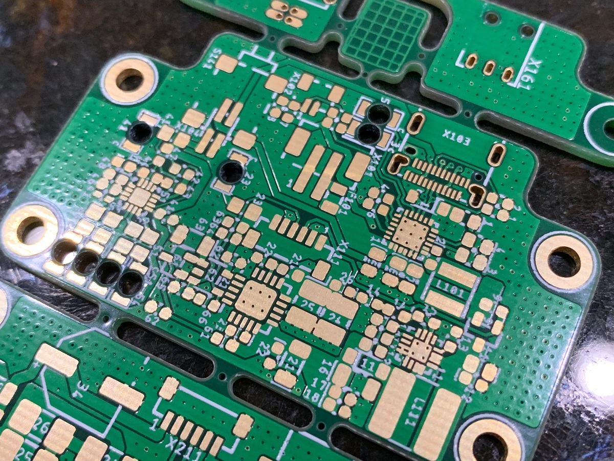
Thes look great - thank you, JPS64!

I better start ordering the parts to make this...
Power management system and DC-DC step up plus regulator:
Thes look great - thank you, JPS64!
I better start ordering the parts to make this...
Attachments
Last edited:
")