Again, with a circuit like this that has limited open loop gain, there's no such thing as just hammering down the distortion with feedback. Also, compromises in the feedback resistors made for sake of stability impact the THD. I'm trying to balance out both of these factors in the simulations. What I find problematic is that the Schitt design features switchable gain. What they do to retain stability margin in both gain settings should prove interesting.
I use the 1V RMS into 32 ohms output level, because that is what Schitt uses to specify their distortion. I would like to match their specs if possible.
A reminder - this is all in the simulation realm. Simulation allows one to do a lot of the grunt work beforehand, but you've still got to build, characterize, and listen to the actual circuit, which probably behave differently than the sim, from parasitic effects if nothing else.
Thanks- there's not all that much under the hood. I suspect the topollogy is similar to the last of the simulations I'll be putting up, but with a different suite of devices.
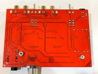
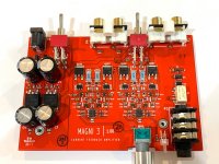
Looks like 8 active devices, 2 bias diodes, and an opamp for the servo. As I suspected, it's surface mount, using the PCB copper for a heat sink. I didn't suspect they'd use D2pack devices at the outputs, though.
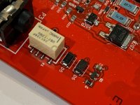
It also looks like they're using the AC wall wart in a voltage doubler configuration to generate the plus and minus rails - a cost-effective approach.
Jason Stoddard says it is a simple half wave rectifier. No doubler.
Magni 3 Impressions | Page 48 | Headphone Reviews and Discussion - Head-Fi.org
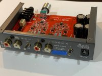
I'll tell you what's in the box...
The rear panel says the wall wart input is 14VAC. My question back then was how does a 14VAC wall wart produce +/-17v rails necessary for the power output that is claimed? The answer I got from Stoddard (the co-founder of Schiit) was the above statement that there was no magic, just a half wave bridge. Your question got me to re-examine it again. So the wall wart has a "14VAC 1500mA 21W" nameplate. My Fluke 116 DMM tells me that it is actually 16.30VAC (no load). The LM317 has +19.8VDC in and +17.50VDC out. The LM337 has -19.65VDC in and -17.11VDC out.
So it does look like a half-wave bridge "doubler" to get 39.45v across both rails from 16.3VAC input (nominal 46VDC under no load). This thing is biased 100mV across the (blue) 4R75 emitter resistors or 21mA quiescent. This is 720mW quiescent dissipation per channel. Feels about right as unit is warm at normal operating temp.
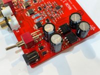
Here are closeup photos, knock yourself out. Let me know if you need any more details or different photo angles. Or even extreme closeups as I have a stereo microscope to really get in there if needed.
Edit, under microscope, I can make out the laser etched markings on the smaller SOT23 units as:
Q101=ABG
Q102=CBG
Q103=CBG
Q104=ABG
(note that the G might be a 6)
I will tell you that the unit is very well engineered for production (made in USA) with 4 screws holding the PCB to the 2 piece chassis, and 4 screws holding the nicely sculpted satin finished aluminum cover to the bottom stamped steel chassis. There are no loose wires that needed to be soldered during assembly - minimal touchwork besides the 8 screws. My measurements show that it is very low distortion but gets ragged with lots of higher order harmonics when pushed up to the higher power levels - usual behavior for Class AB amps. It sounds very nice and you will behard pressed to make one for yourself for under $100 in parts. My guess is that the BOM (not including chassis or wall wart) would cost you probably easily $80 to $100 alone in singles from Mouser or Digikey.
The rear panel says the wall wart input is 14VAC. My question back then was how does a 14VAC wall wart produce +/-17v rails necessary for the power output that is claimed? The answer I got from Stoddard (the co-founder of Schiit) was the above statement that there was no magic, just a half wave bridge. Your question got me to re-examine it again. So the wall wart has a "14VAC 1500mA 21W" nameplate. My Fluke 116 DMM tells me that it is actually 16.30VAC (no load). The LM317 has +19.8VDC in and +17.50VDC out. The LM337 has -19.65VDC in and -17.11VDC out.
So it does look like a half-wave bridge "doubler" to get 39.45v across both rails from 16.3VAC input (nominal 46VDC under no load). This thing is biased 100mV across the (blue) 4R75 emitter resistors or 21mA quiescent. This is 720mW quiescent dissipation per channel. Feels about right as unit is warm at normal operating temp.
Here are closeup photos, knock yourself out. Let me know if you need any more details or different photo angles. Or even extreme closeups as I have a stereo microscope to really get in there if needed.
Edit, under microscope, I can make out the laser etched markings on the smaller SOT23 units as:
Q101=ABG
Q102=CBG
Q103=CBG
Q104=ABG
(note that the G might be a 6)
I will tell you that the unit is very well engineered for production (made in USA) with 4 screws holding the PCB to the 2 piece chassis, and 4 screws holding the nicely sculpted satin finished aluminum cover to the bottom stamped steel chassis. There are no loose wires that needed to be soldered during assembly - minimal touchwork besides the 8 screws. My measurements show that it is very low distortion but gets ragged with lots of higher order harmonics when pushed up to the higher power levels - usual behavior for Class AB amps. It sounds very nice and you will behard pressed to make one for yourself for under $100 in parts. My guess is that the BOM (not including chassis or wall wart) would cost you probably easily $80 to $100 alone in singles from Mouser or Digikey.
Attachments
-
 Schiit-M3-Amp-Rearpanel--01.jpg279.3 KB · Views: 267
 -
 Schiit-M3-Output-Relay-06.jpg336.8 KB · Views: 146
 -
 Schiit-M3-Amp-Core--05.jpg520.5 KB · Views: 271
 -
 Schiit-M3-Amp-PCB-Rect-PSU-04.jpg340.8 KB · Views: 264
 -
 Schiit-M3-Amp-PCB-bottom-03.jpg304 KB · Views: 270
 -
 Schiit-M3-Amp-PCB-top-02.jpg351.3 KB · Views: 276
Last edited:
The output stages are CFP using 2SA1552T, 2SC4027T output devices. The TL081 is presumably DC servo. Presumably "all discrete bipolar" doesn't include the servo for marketing reasons!
The bias stability I think just relies on the proximity of the two diodes to the output transistors and emitter resistors, perhaps not very great, but the temperature excursions are probably not an issue in practice with headphones (and large value emitter resistors).
I suspect the OS is pretty linear with those high gain transistors (the T suffix are 200--400 gain bracket)
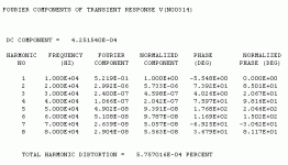
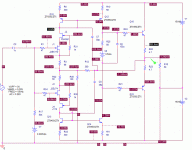
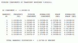
Here is my read of the schematic, with the values I can read filled in. I suspect that the biasing diodes are dual, otherwise the output doesn't bias up decently, and the THD is poopy... The compensation scheme is interesting, I'll mess with pulse response later - the two caps are place holders. The distortion meets their spec so far. I'll mess with it more later.
Attachments
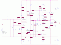
Nice work. Will you start using actual BJT models of the parts in the board - or at least closer in size as you have what looks like SOT23 all along the amp. The drivers are SOT223 and outputs are DPAKs (essentially snipped TO220). Let me k ownif yiu need any closer look on a part under microscope. Or voltage probe at certain junction.
The parts I'm currently using are all in e-line packages, good for about 1/2W on a good day. I have no intention of slavishly copying the Schitt circuit, but instead want to use it as a jumping-off point for something of my own. Their take on compensation and their position for the insertion of the servo are a nice haul from this effort. I might entertain a through-hole design using the Zetex parts and some TO-126 output devices.
This schematic has absolutely nothing to do with the Schitt amp any more, but it's an interesting excursion in itself. I may try simulating another design using common emitter VAS instead of the current mirror approach. In practice, I would use some the Fairchild/ON Semi KSA KSC devices in TO-126 package as output devices, since they will be able to dissipate the needed power with a nominal heat sink, and have the gain/ft appropriate for a design like this.
Attachments
The Even More Amazing Schiit Magni 3+
Time to bust out the credit card again wrenchie.
Without a shadow of a doubt, you're going to want to look extra hard through that ole' pipe wrench in our avatar for this find!
Jason Stoddard and company has "up the ante" again with the even more powerful Magni 3+ current-feedback amplifier--My Oh My.")
Despite being even more powerful than the original Magni 3, pricing still remains at the same giveaway price of only $99 plus shipping and taxes.
Time to "look under the hood" of this one as well and see if you can match it's performance...LOL.
Take care and Merry Christmas.
Time to bust out the credit card again wrenchie.
Without a shadow of a doubt, you're going to want to look extra hard through that ole' pipe wrench in our avatar for this find!
Jason Stoddard and company has "up the ante" again with the even more powerful Magni 3+ current-feedback amplifier--My Oh My.
Despite being even more powerful than the original Magni 3, pricing still remains at the same giveaway price of only $99 plus shipping and taxes.
Time to "look under the hood" of this one as well and see if you can match it's performance...LOL.
Take care and Merry Christmas.
Detailed subjective review of Magni 3+ against Magni Heresy (opamp-based) and others here : Schiit Magni 3+ & Magni Heresy - Headphone Amplifier - Review & Compar
Teardown-lite of Magni 3+ : Schiit Magni 3+ Headphone Amp Teardown | Audio Science Review (ASR) Forum
Just pulled the trigger and nabbed one... Sometimes it pays to wait.
Still want to build your clone?
I never wanted to build a clone as such. The Magni will serve as as a listening example for that particular price point. I have 4-5 other designs in the pipeline (distinctly different) that all will require tweaking, boxing, and listening. I may also build a few of the current feedback designs I've detailed here.
Right now, though, I'm building Christmas presents.
Right now, though, I'm building Christmas presents.
I'll tell you what's in the box...
The rear panel says the wall wart input is 14VAC. My question back then was how does a 14VAC wall wart produce +/-17v rails necessary for the power output that is claimed? The answer I got from Stoddard (the co-founder of Schiit) was the above statement that there was no magic, just a half wave bridge. Your question got me to re-examine it again. So the wall wart has a "14VAC 1500mA 21W" nameplate. My Fluke 116 DMM tells me that it is actually 16.30VAC (no load). The LM317 has +19.8VDC in and +17.50VDC out. The LM337 has -19.65VDC in and -17.11VDC out.
So it does look like a half-wave bridge "doubler" to get 39.45v across both rails from 16.3VAC input (nominal 46VDC under no load). This thing is biased 100mV across the (blue) 4R75 emitter resistors or 21mA quiescent. This is 720mW quiescent dissipation per channel. Feels about right as unit is warm at normal operating temp.
Here are closeup photos, knock yourself out. Let me know if you need any more details or different photo angles. Or even extreme closeups as I have a stereo microscope to really get in there if needed.
Edit, under microscope, I can make out the laser etched markings on the smaller SOT23 units as:
Q101=ABG
Q102=CBG
Q103=CBG
Q104=ABG
(note that the G might be a 6)
I will tell you that the unit is very well engineered for production (made in USA) with 4 screws holding the PCB to the 2 piece chassis, and 4 screws holding the nicely sculpted satin finished aluminum cover to the bottom stamped steel chassis. There are no loose wires that needed to be soldered during assembly - minimal touchwork besides the 8 screws. My measurements show that it is very low distortion but gets ragged with lots of higher order harmonics when pushed up to the higher power levels - usual behavior for Class AB amps. It sounds very nice and you will behard pressed to make one for yourself for under $100 in parts. My guess is that the BOM (not including chassis or wall wart) would cost you probably easily $80 to $100 alone in singles from Mouser or Digikey.
what is the reason for burned output transistors in several devices of the same model ?
For images go to
https://www.diyaudio.com/forums/hea...ffer-stage.html?posted=1&posted=1#post6392936
Last edited:
- Status
- This old topic is closed. If you want to reopen this topic, contact a moderator using the "Report Post" button.
- Home
- Amplifiers
- Headphone Systems
- What's in the box?