You can get ready made 3045/3094 which are 78xx/79xx pin compatible.
There are no better regulators, and the current limit works.
Just a switch for resistors, or even a pot will allow you to change the current limit at will.
And they don't need large caps, as already said.
I use RCRC for years. It triggers in 20mS for 15V. For me no issue.
It depends on how you set the RC time constant, and trigger level.
So I see no argument to change my own approach.
For me it does exactly what I what it to do.
But do what suits you best.
Cheers,
Patrick
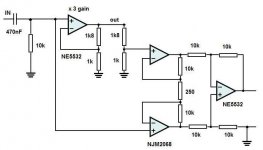
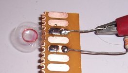
Since no-one has any comments on the instrumentation amp, I went ahead and build a test circuit.
I only had 2 dual opamps to play with , NE5532 & NJM2068 , not the best choice for it , but used them anyway.
Well it's hard to test them . They do exactly what they're supposet to do, amplify the difference between in and out . I matched all the resistors as close as posible , and got with a gain of around 80x , 70mV dc at the output of the InAmp , regardless of a signal at the input , < 1mV ac. When I put resistors over the 1k8 to the InAmp , there was a big ac voltage in tune with the music , big enough to trigger a window comparator . So it does work.
An 1,5 V dc voltage at the input of the amp (after the cap) , didn't do anything , because the NE5532 just amplifies it with the ac of the music on top . The InAmp only compares in and output , it only detects DC if the DC is not at the input , which it shouldn't be after the input capacitor.
Like I said it is hard to test a DC at the output , without having any on the input , and of course not breaking the opamps trying to so.
Any suggestions how to test output faults without wrecking the opamps ?
Attachments
You can get ready made 3045/3094 which are 78xx/79xx pin compatible.
There are no better regulators, and the current limit works.
Good for you , Patrick.
I just did these test with about 15 mA and 9V over the LM317/337 in TO220, and with only about 135mW , they were warm . I can't imagine how hot your 3045/3094 will be with that little 1 mm2 thermopad . Because who needs AL/Cu heatsinks when 35-70 µm Cu on epoxy board is soooo much better.

I live in the tropics , it's always hot . Cooling of electronics is even more important here .
Somehow I doubt your detector switches at only 20ms and not getting into trouble with large < 100hz signals. but if you say so....
Interestingly enough, Rod Elliott suggests that RCRC is worse than RC for DC protection in terms of speed and D. Self shows in its amplifier design book that RCRC or even active filters are slower than a simple RC filter.
An interesting trick mentioned recently by PRR is to deliberately make your amp with a somewhat high large signals output impedance, by using large emitter resistors or a resistor inside a feedback loop. This will limit the current available in case of a fault.
An interesting trick mentioned recently by PRR is to deliberately make your amp with a somewhat high large signals output impedance, by using large emitter resistors or a resistor inside a feedback loop. This will limit the current available in case of a fault.
An instrumentation amplifier for that purpose is cumbersome, overkill and unpractical.
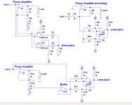
There is a much simpler solution (implemented in some clipping detectors): use two offset-shifted comparators to compare the inverting and non-inverting inputs.
Where are you going to find offset-shifted comparators?
A way of implementing them is to use opamps with offset adjustment pins accessible, and to deliberately drive them into offsets of opposing polarities.
Once it is done, you combine the outputs with an or gate (with diodes or logic circuits), and you can process the signal digitally to your taste: delays, muting period, cumulative on time, etc.
As single opamps with all pins accessible become rare, there are workarounds, and you can use directly a true comparator.
The simplest case is the inverting amplifier.
For a regular NI amp, you need an additional buffer.
Note that you have a complete freedom of choice regarding the thresholds, etc., and you do not need a single precision resistor.
The detection will always work, even if the supply rails sag etc.
Attachments
^ The idea of just comparing in and output with one (or in your case 2) opamps/comparators was my first idea : https://www.diyaudio.com/forums/solid-state/209896-amplifier-dc-protection-3.html
But I had to abandon that because even idle with no signal in , 0V , the slightest offset (which is not constant >> tempco) , makes the comparartor switch (or the opamp with full gain) . Making the opamps not switch to the rails , means limit the gain and then it becomes a differential amp with low input impedance . Ad 2 high impedance buffers and it is an instrumentation amp. And that's where I am now.
An instrumentation amplifier for that purpose is cumbersome, overkill and unpractical.
Compared to the RC or RCRC types , it is only 3 opamps or 1 InAmp more. Cheap and low quiescent current ones with Jfet input like TL072 will do and hopefully won't degrade the input signal. SMD R's you buy per 50 or 100, so selecting with the same exact value is no big deal. The InAmp doesn't have to be that accurate in offset or gain . Thresholds are ballpark not to the mV accurate.
I just wanted an alternative or novel way for a faster fault detection than the RC or servo cicuits.
The problem is I don't have an oscilloscope to see and test what is really going on at the InAmp's output. A DVM only says so much (or little). Are there higher frequency glitches ?
I can't put a flipflop or timer after it for testing because I can only buy them in SMD , and cutting a PCB for it is too difficult . ( for a simple circuit like the DeNoiser it is doable but not for smd IC's).
https://www.diyaudio.com/forums/solid-state/209896-amplifier-dc-protection-3.html
Interestingly enough, Rod Elliott suggests that RCRC is worse than RC for DC protection in terms of speed and D. Self shows in its amplifier design book that RCRC or even active filters are slower than a simple RC filter.
Interesting link and a good read especially the part about relays . Who knew the diode extends the relay's off time ? Now I wonder how much more than the 5ms it is going to take for those small signal relays I just bought.
The first relays I bought for switching inputs of my preAmp , were Siemens small signal print relays. Although they were used in a closed alunimium case , it still irritantes me to hear them switch. The ones I bought now are soooo small and much more silent :Takamisawa NA24W = Fujitsu. Awesome ! I use them in series on around 48V, seems to work.
The thing you miss is the offset added to the comparators, exactly to prevent such a situation.But I had to abandon that because even idle with no signal in , 0V , the slightest offset (which is not constant >> tempco) , makes the comparartor switch (or the opamp with full gain) .
You can make the window as large or narrow as you like, to take into account variations, etc.
You do not seem to realize that if offset is a problem with the comparators, it will be exactly the same with the instrumentation amplifier, except it will be worse, because you throw the uncertainty of a second resistive divider into the equation....
Analyze your circuit properly, and you will see that I am right
I'm not worried about the offset of the comparators , but about offset of the HPamp when using comparators or opamps in open loop for detection. Even using opamps for the HPamp with 100's of uV offset (like OPA1612), may make the comparators switch even with hysteresis. Maybe not in your design but I don't see it.
Because of the limited gain of the InAmp , offset of the HPamp is irrelevant . A big static dc offset of 2 mV x a gain of 80 , gives a stable voltage of 160mV at the InAmp output which can be easily compensated .
I don't see the second resistive divider as an uncertainty.
The only concern I have is about false triggering of the detector. And for that I need an oscilloscope.
You do not seem to grasp the concept of a window comparator.
Here is one of the examples rendered functional:
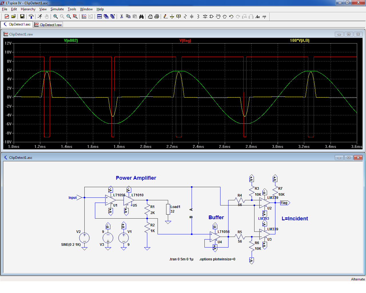
In this case, the window set by R4, R5 is ~ +/-50mV.
The 100*V(A,B) trace is the magnified differential signal of the PA, normally very small, but increasing very quickly in case of clipping.
The advantage of such a scheme is that you do not add the uncertainties of a second resistive divider: make the calculations, and you will realize that tiny errors have a huge impact, because you subtract quantities.
No such thing here, and you can adjust the thresholds exactly without an oscilloscope. You could even opt for different thresholds for the + and - polarities if you fancy it.
The output is a clean digital signal, ready for further processing
Here is one of the examples rendered functional:
In this case, the window set by R4, R5 is ~ +/-50mV.
The 100*V(A,B) trace is the magnified differential signal of the PA, normally very small, but increasing very quickly in case of clipping.
The advantage of such a scheme is that you do not add the uncertainties of a second resistive divider: make the calculations, and you will realize that tiny errors have a huge impact, because you subtract quantities.
No such thing here, and you can adjust the thresholds exactly without an oscilloscope. You could even opt for different thresholds for the + and - polarities if you fancy it.
The output is a clean digital signal, ready for further processing
Attachments
A warning: the above is just an illustration of a concept, not a ready-to-use project (it's not mine).
To make it actually functional, you need to do some homework: for example, bipolar comparators have bias currents varying with the input voltages, differential or common mode.
I have included a buffer in the feedback arm of the comparison, because it would be difficult (but possible) to do otherwise, but the circuit assumes a low-impedance source.
With semiconductors, it will normally always be the case, but a tube preamp could have a 10K impedance, in which case the LM339 (or 393) will generate non-negligible additional distortions.
A buffer might also be needed there, or a better comparator like the TLC374 could be used.
Similarly, the thresholds or resistance levels around the comparators need to be estimated in a deterministic way: for this example, I just threw in convenient values, but if you intend to actually build and use the thing, you need to spend some time thinking about the details (valid for any project)
It's not simply a signal strength detector: from 0 to 100% of the dynamic range, its output will stay completely inactive, but it will deliver pulses as soon as 101% (or any other value) is reached.
That is exactly what you initially wanted:
You can add a RC, but it will have to be a small one if you need a reaction time <1ms.
There are many other possibilities: one-shots, digital counters and logic, or even a µcontroller.
It depends on the level of "intelligence"/sophistication you want to achieve
That is exactly what you initially wanted:
like distortions when you
drive the output to the rails.
You can add a RC, but it will have to be a small one if you need a reaction time <1ms.
There are many other possibilities: one-shots, digital counters and logic, or even a µcontroller.
It depends on the level of "intelligence"/sophistication you want to achieve
^ Well I've been looking at it for a while , and I'm confused about the resistors going from the supply rails to the buffer's output . Will have to do some more thinking before I get it ...
"like distortions when you drive the output to the rails."
This is not what I was after , but it is inherent to the circuit , when comparing a pristine input signal with a distorted output.But thanks for your input LV , it gives me something to think about.
"like distortions when you drive the output to the rails."
This is not what I was after , but it is inherent to the circuit , when comparing a pristine input signal with a distorted output.But thanks for your input LV , it gives me something to think about.
Input and output comparison would be the end-all for protection.
Its a good start, but you might want output device protection too, and possibly thermal modelling of tweeter coils to prevent tweeters from frying, and thermal overload sensing on main heatsink and possibly on the power transformer.
With a heat capacity of 380J/°K*kg, this means that in order not to exceed a temp rise of 150°C for a single pulse in adiabatic conditions, the energy must be < 0.01*150*0.38 = 0.57J, or 570mJ.
The estimation is conservative, and a number of heat sinks, like glue, varnish or mylar have not been taken into account.
I have made a real-world sanity check: I have applied pulses of increasing energy to the VC illustrated (probably one of the smallest size for out of the ear HP).
I used calibrated capacitors charged at a calibrated voltage, and I started at 100mJ.
To best simulate of faulty amplifier, I charged the capacitors at around 14V.
For example, for 100mJ, 0.5*14.1²*1000µF=100mJ.
I used Ecaps for convenience, but since they have a wide tolerance and a relatively poor charge/restitution efficiency, I selected them, measuring their capacitance based on energy efficiency, and I fined-tuned the result by adjusting the charging voltage.
This means that the actual voltage ranges between 13 and 15V.
For each energy level, I applied two pulses, with a 10s pause in between.
I inspected visually the coil during and after the events, and measured its integrity (it measured 30 ohm at the start of the test).
I tested 100mJ, 200mJ, 300mJ, 400mJ, 500mJ, 750mJ, 1J, and finally 2J.
The coil stayed apparently intact up to 1J, with no visual or electrical change.
At 2J, the first pulse resulted in a slight distortion, and after the second pulse it was completely warped:
This means that up to 1J seems to be safe, but there might also be undetectable deformations at this level which would impair its functionality.
In addition this test only exercises the thermal resilience of the coil assembly.
If the coil is sent flying at several m/s towards an obstacle, it could be mechanically damaged.
To summarize, from a purely thermal POV, 500mJ should generally be safe enough.
Mechanical effects would depend very much on the construction and are not easily predictable.
Electrically, the 2J were unable to affect it: it stayed at 30 ohm.
Attachments
Thanks! very helpfulI have made a real-world sanity check

For each energy level, I applied two pulses, with a 10s pause in between.
How wide were those pulses ?
The pulse length was decided by the energy storage capacitors: for the 100mJ, 1000µF means a RC product of 30ms with the 30Ω resistance.
Since the waveform is exponential, most of the energy will have been delivered by then.
So, 1J=>300ms and 2J(damage level)=>600ms (with a 22,000µF cap)
Since the waveform is exponential, most of the energy will have been delivered by then.
So, 1J=>300ms and 2J(damage level)=>600ms (with a 22,000µF cap)
- Status
- This old topic is closed. If you want to reopen this topic, contact a moderator using the "Report Post" button.
- Home
- Amplifiers
- Headphone Systems
- Fast DC protection for HPamps.