Hello dear friends,
I assembled a DIY kit called "Quasar kit No 1215".
Can be found here: Stereo Line Level Audio Preamp - Headphone Amplifier | Smart Kit 1215
PCB board and parts were included, but without power supply and transformer.
The power supply I used is a common LM317/337 board.
Transformer is 18-0-18 Volts on the secondary, rated @ 50VA.
I've been trying it with a pair of Sennheiser HD559 (50 Ohms) and a Behringer U-Phoria UMC204HD signal source for the last 2-3 days and I'm quite pleased by what I hear. Seems to be completely silent, with around 7mV measured DC offset on the output and with plenty of power.
Without much frame of reference apart from my Behringer UMC204HD and Yamaha RX-V663 headphone outs, all I can say is that this kit provides greater detail and depth of sound. I enjoy it so far.
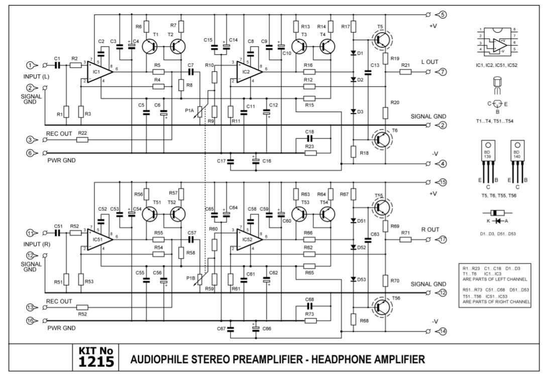
The kit was accompanied by a manual that includes the following schematic:

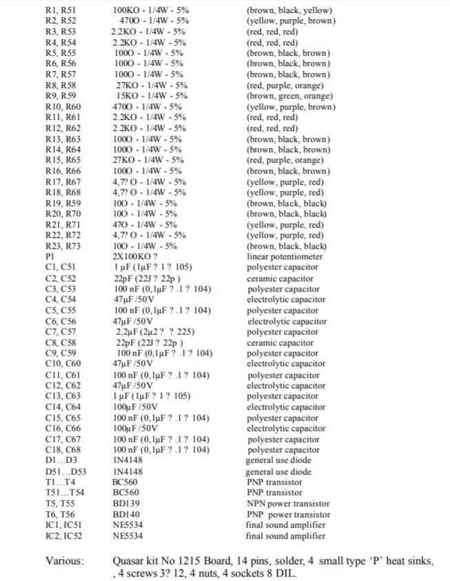
Parts list (typo: R59 is actually R69):
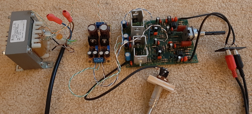
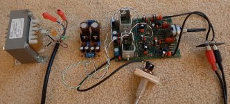
Here's the build without enclosure:
Hope the above info to be interesting/useful to any folks.
Also, I wonder if anybody has any particular thoughts, on what could be improve upon on this kit.
Suggestions on better/more suited parts or any modifications would be greatly appreciated!
Thanks for reading.
Kind regards,
Nick.
I assembled a DIY kit called "Quasar kit No 1215".
Can be found here: Stereo Line Level Audio Preamp - Headphone Amplifier | Smart Kit 1215
PCB board and parts were included, but without power supply and transformer.
The power supply I used is a common LM317/337 board.
Transformer is 18-0-18 Volts on the secondary, rated @ 50VA.
I've been trying it with a pair of Sennheiser HD559 (50 Ohms) and a Behringer U-Phoria UMC204HD signal source for the last 2-3 days and I'm quite pleased by what I hear. Seems to be completely silent, with around 7mV measured DC offset on the output and with plenty of power.
Without much frame of reference apart from my Behringer UMC204HD and Yamaha RX-V663 headphone outs, all I can say is that this kit provides greater detail and depth of sound. I enjoy it so far.
The kit was accompanied by a manual that includes the following schematic:
Parts list (typo: R59 is actually R69):
Here's the build without enclosure:
Hope the above info to be interesting/useful to any folks.
Also, I wonder if anybody has any particular thoughts, on what could be improve upon on this kit.
Suggestions on better/more suited parts or any modifications would be greatly appreciated!
Thanks for reading.
Kind regards,
Nick.
Last edited:
Attachments no workee.
Not a major problem, mind you, as you can download the manual.
That's not a bad little circuit, really. They even went to the trouble of including a dedicated power ground. If the HD559 is anything like its predecessor, a 47 ohm output impedance probably is a factor of 10 too high though (making sound overly boomy) - I'd adjust the value of R21/71 accordingly, which should still easily be high enough to keep potential oscillation issues at bay (with a Cc = C8/C58 of 22 pF, the opamp itself should be unity gain stable, and gain is 2 here).
The TO-126 output transistors are dissipating a good 0.5 W each and would be cooking along at 80°C "barefoot" - not a super critical temperature, but I'd still consider either buying or making some matching small heatsinks. Actually the manual even says that heatsinks are included, though the picture on their website confusingly shows none. (It doesn't have to be anything fancy, even 30 K/W would drop temps by over 30 K.)
The circuit includes a current source (or rather current mirror) for opamp Class A biasing, but confusingly, the current would appear to come out as about 2/3 of a milliamp, which seems a tad on the low side. Usually it would not be uncommon to see up to 5 mA, depending on what thermals will allow ("go broke or go home" generally is the motto here). I'd suggest upping R14/R64 to 470 ohms (maybe up to 1 kOhm) and see where this gets you. (Measure voltage across R6 and use Ohm's law - I(R6) = V(R6)/R6)
Gain staging is like Rod Elliott's preamp at 6 + 6 dB - not much wrong with that, assuming 12 dB of total gain is enough for you. Given a nominal output level of +3 dBu (~1.1 Vrms) on the interface and your relatively sensitive headphones (108 dB / 1 Vrms), this is very likely to be the case.
They are using the el cheapo way of making a "log" pot - a linear pot loaded by a resistor. See here. This can stay if you are fine with the relatively limited adjustment range provided by this solution, though if Rod Elliott is to be believed, a 50k pot would result in a more desirable characteristic than the 100k they used.
What kind of supply voltage did you set? With an 18-0-18 xfmr, I imagine you could go as high as +/-20 V or so, a good bit higher than you really need (unless you are planning a foray into 600 ohm cans or isodynamics). 50 VA also seems a bit oversized. 20 VA 15-0-15 and +/-15 V should generally do fine for an amp like this. Does the LM317/337 board include ADJ pin capacitors?
Found another tpyo in the parts list - 47 Ohm resistors R21/R71 are listed as "(yellow, purple, red)", like the 4.7 kOhms. Should be (yellow, purple, black). Probably not a big deal if you are populating in ascending order, besides see above.
Last edited:
Thanks a lot for the reply.
And forgive my previous post, regarding attachments.
They do not work as they should.
It's my fault since I have little experience with this forum mechanics.
Still learning...
Here, I re-post the above attachments:
Kit schematic.
Parts list (typo: R59 is actually R69).

The build without enclosure.

And forgive my previous post, regarding attachments.
They do not work as they should.
It's my fault since I have little experience with this forum mechanics.
Still learning...
Here, I re-post the above attachments:
Kit schematic.
Parts list (typo: R59 is actually R69).
The build without enclosure.
Attachments

HD 559 has an impedance of 50 Ohms, according to the manufacturer....If the HD559 is anything like its predecessor, a 47 ohm output impedance probably is a factor of 10 too high though (making sound overly boomy) - I'd adjust the value of R21/71 accordingly, which should still easily be high enough to keep potential oscillation issues at bay (with a Cc = C8/C58 of 22 pF, the opamp itself should be unity gain stable, and gain is 2 here).
I was actually a bit worried about the impedance matching with these headphones, since the output impedance given in the PDF manual is stated @ 100 Ohms. It's actually described as "combined(?) output resistance".
However, the R21/71 is 47 Ohms as you observed.
Would you think it'd be OK to change it to around 4.7 Ohms?
Would it be enough to prevent any possible oscillations at that value?
Although they are mentioned in the kit, they weren't included in the parts.The TO-126 output transistors are dissipating a good 0.5 W each and would be cooking along at 80°C "barefoot" - not a super critical temperature, but I'd still consider either buying or making some matching small heatsinks. Actually the manual even says that heatsinks are included, though the picture on their website confusingly shows none.
I had to provide my own 4 heat sinks (you can see them in the picture i re-attached).
And you are absolutely correct.
They are essential since these transistors tend to heat up pretty quickly.
I'll measure the current as is and I'll also try what you suggest.The circuit includes a current source (or rather current mirror) for opamp Class A biasing, but confusingly, the current would appear to come out as about 2/3 of a milliamp, which seems a tad on the low side. Usually it would not be uncommon to see up to 5 mA, depending on what thermals will allow ("go broke or go home" generally is the motto here). I'd suggest upping R14/R64 to 470 ohms (maybe up to 1 kOhm) and see where this gets you. (Measure voltage across R6 and use Ohm's law - I(R6) = V(R6)/R6)
Will report back on the current I get.
Actually, the HD 559 is being amplified to a satisfying degree right now.Gain staging is like Rod Elliott's preamp at 6 + 6 dB - not much wrong with that, assuming 12 dB of total gain is enough for you. Given a nominal output level of +3 dBu (~1.1 Vrms) on the interface and your relatively sensitive headphones (108 dB / 1 Vrms), this is very likely to be the case.
I wonder how the device will be able to cope with a higher impedance headphone (like in the range of 300 Ohms)?
So, are you suggesting that I should go for a 50K Ohms linear pot instead?They are using the el cheapo way of making a "log" pot - a linear pot loaded by a resistor. See here. This can stay if you are fine with the relatively limited adjustment range provided by this solution, though if Rod Elliott is to be believed, a 50k pot would result in a more desirable characteristic than the 100k they used.
The potentiometer is actually one of the things I was thinking to replace.
Forgive my questions, but I am a complete novice when it comes to electronics.
I am not sure they are adjustable capacitors on it(?).What kind of supply voltage did you set? With an 18-0-18 xfmr, I imagine you could go as high as +/-20 V or so, a good bit higher than you really need (unless you are planning a foray into 600 ohm cans or isodynamics). 50 VA also seems a bit oversized. 20 VA 15-0-15 and +/-15 V should generally do fine for an amp like this. Does the LM317/337 board include ADJ pin capacitors?
The little LM317/337 board does include little pots that you can use to adjust the output voltage on each rail.
They look like these:
An externally hosted image should be here but it was not working when we last tested it.
The input DC voltage suggested by the manual is: +15, -15 (100mA).
So, I adjusted both to 15.3 Volts.
You are absolutely right.Found another tpyo in the parts list - 47 Ohm resistors R21/R71 are listed as "(yellow, purple, red)", like the 4.7 kOhms. Should be (yellow, purple, black). Probably not a big deal if you are populating in ascending order, besides see above.
The color coding is wrong there.
-------------------
Thanks again for your valuable explanations and suggestions.
Kind Regards,
Nick.
Last edited:
I do think so. In simulation I rarely had problems when using more than 1, maybe 2 ohms. (Speaker power amps cannot afford values this high so tend to use more elaborate solutions.)However, the R21/71 is 47 Ohms as you observed.
Would you think it'd be OK to change it to around 4.7 Ohms?
Would it be enough to prevent any possible oscillations at that value?
Just fine, I imagine. We are talking 102-103 dB/V typ, or ~6 dB less. Now the HD559 is currently experiencing close to 6 dB of attenuation due to the 47 ohm of output impedance, so basically levels would be quite similar to what they are now.Actually, the HD 559 is being amplified to a satisfying degree right now.
I wonder how the device will be able to cope with a higher impedance headphone (like in the range of 300 Ohms)?
Hmm. On reading Rod Elliott's article again, the combination of 100k pot + 15k found here actually was what he used to recommend and is "near ideal in listening tests", so we can assume the circuit designer read this.So, are you suggesting that I should go for a 50K Ohms linear pot instead?
The potentiometer is actually one of the things I was thinking to replace.
One advantage of linear pots is that they are considerably simpler and much less prone to channel tracking issues than log pots, which is a definite advantage when using cheap parts (considering that headphones will show up even <1 dB of imbalance quite easily). Said channel tracking issues also have a tendency to get worse for lower values, so the 10k or 20k you would need (plus a higher value of R9) wouldn't fare quite as well at low volume settings as more traditional 50k or even 100k values. Mind you, these tend to occur below the -40 dB mark, which is difficult to even reach reliably with the "fake log" solution.
Ultimately, if you are happy with the volume adjustment range provided now, I would leave the pot as-is. Otherwise I'd consider a good quality 10k-20k log pot with a higher value of R9.
There is another problem I didn't notice before - the volume pot is DC-coupled to the 5534 input. You wanting to replace the pot wouldn't happen to be because it's noisy? Granted, this could be because of a cheap old part (I once had to treat a cheap Chinese pot with suitable contact cleaner after less than two years or so, it was absolutely fine for years after that and probably still is today), but having opamp input bias current running over the pot isn't going to do it any favors. Oh boy, that'll be a bit of a hack.
Obviously, you could replace the 5534 (IC2) with a part that either has a FET input or bias current cancellation. Since, however, highish input bias current is one of the few vices of this part and upgrade options are somewhat limited and Not Cheap (I mean, you could try the trusty old LM356, which while substantially noisier, is an OK part at least, an an OP134 would be only moderately expensive), I would rather hack in a coupling capacitor (maybe 4.7-10 µF electrolytic, ideally two back-to-back). Do you see any way of easily adding one between the pot wiper and the R9-R10 junction? If that's not feasible, I'd try lifting one end of R10 and adding it in series with that, but then you'll need an additional resistor to ground (maybe 100k?) as the opamp input must not be left floating, it needs that input bias current after all.
I am not sure why the circuit designer did this. They seemed to have been an electrolytophobe with a penchant for film coupling capacitors, so I guess they reckoned placing C7 on the input side of the pot would give it lighter loading and hence lower bass cutoff frequency, totally forgetting about input bias current. Possibly the circuit was originally supposed to use a FET input part like OPA132/134 there and they settled for the cheap and good - but bipolar input - '5534 instead without accounting for the implications.
No, not adjustable capacitors - capacitors connected between the regulator ADJ pin and ground (C_adj)! See LM317 datasheet. A proper low-noise reg setup would have something like 10 µF there. They are not very low noise without.I am not sure they are adjustable capacitors on it(?).
This will work fine, though I reckon the regulators will be dropping somewhere around 9 V with your relatively high secondary transformer voltages, which is not going to win any kind of efficiency prizes. You also don't necessarily want these regulators to drop more than about 8 V or so as they have a tendency to oscillate then.The little LM317/337 board does include little pots that you can use to adjust the output voltage on each rail.
They look like these:
An externally hosted image should be here but it was not working when we last tested it.
The input DC voltage suggested by the manual is: +15, -15 (100mA).
So, I adjusted both to 15.3 Volts.
The upper limit for operating voltages of the amplifier circuit is given by the 5534s at +/-22 V max, though they do tend to become a bit toasty at this point and most people would stick with a maximum of +/-20 V. I would see what sort of unregulated input DC voltages you get and dial in about 5 V less (as long as that gets you to 20 V tops). As the regulators need a minimum drop of around 2 V, that should give you quite a bit of headroom for potential ripple and drooping voltage under load.
BTW, I got the current source reference current wrong earlier - it would be about 1.1 mA (@+/-15 V) rather than the 2/3 of a mA as stated. Given that, I would go for R14 = 330 ohms instead. I also forgot that the gain stage opamp has the same kind of circuit. Class A bias current seems insufficient to cover worst-case signal levels there as well, and I would up R7 to 220-330 ohms.
Speaking of resistors, the ones coming with the kit look like they may be of the lowly carbon composition variety. If you happen to have some 2.2 kOhm metal film parts kicking around (the regular cheap blue 1% Yageos will do fine), I would consider at least replacing R11/R12.
It is nice that they have C13 there, but its effect could be extended to lower frequencies if you managed to squeeze in a little electrolytic in parallel in the area (maybe 100 µF @ 6.3-10 V, polarity observing).
(Replicate on right channel.)
Last edited:
Dear Sgrossklass,
Thanks again for your valuable input.
They are of great help.
Please allow me to ask some more questions.
----------
-Regarding resistances R6, R56:
Actual figures:
I(R6) = 1.15mA
I(R56) = 1.26mA
I(R7) = 1.07mA
I(R57) = 1.07mA
So, should I proceed as per your suggestion and change R6, R56, R7, R57 values from 100Ω to 330Ω?
---------------------
-Regarding R21, R71:
Is it be possible safely go lower than 4.7Ω value (reminder: original value is 47Ω)?
If so, I could go with half the 4.7Ω value.
Would I achieve a greater damping factor that way?
---------------------
-Regarding the potentiometer:
It isn't really causing me any noise issues.
I was thinking to replace it for another reason.
Wanted to omit those R9, R59 resistors entirely and use it as a linear pot, since I tend to prefer the behaviour of linear potentiometers for volume control.
After removing those resistors, maybe I could replace the existing pot with a linear potentiometer of a bit better quality.
Since I have a linear Bournes 50kΩ at hand, can I use that after removing the resistors?
If it ain't right I can always buy a better quality 100kΩ one.
---------------------
-Regarding bias current through the potentiometer:
As you mentioned, the bias current is going through the potentiometer.
Is it critical that bias current should not flow through that pot?
I ask this since I want to remove the R9, R59 (in order to use the pot as linear again).
If I understand correctly, removing those resistors would create the need for a new path to ground for the +IC2 input. It shouldn't be left floating as you mentioned.
So basically could I just leave the bias current flow through that potentiometer?
That way, I'd be able to remove the R9, R59, making use of the pot as linear again, without adding a capacitor between wiper and + IC2 input.
I'm not sure whether this is actually prudent (or even possible), but it'd certainly simplify things.
Please forgive my confusion.
I'm in the process of learning.
---------------------
-Regarding the capacitor C7, C57 (2.2μF):
I really never understood its function. Is it absolutely essential there?
If I keep it, I was thinking of enlarging its capacity a bit.
Just to give the AC signal a bit more 'space' (extend the effect a bit lower).
Was contemplating of using a Vishay MKT-1813 6μF @ 100V for that.
What are your thoughts?
Again, forgive me but I am a novice.
---------------------
-Regarding the capacitor C13, C63 (1μF):
You mentioned the addition of an 100μF electrolytic in parallel.
What's would be the right polarity for them on the schematic?
I can't figure it out since the schematic only uses non-polars there.
Also, would it be of any benefit if I just replaced the originals with non-polar of greater capacity (i.e. 10μF)?
---------------------
- Also, regarding C1, C51, R2, R52:
I was thinking of completely omitting those capacitors(and the resistors) from the input.
I'm using this headphone amp exclusively with a source that has a zero measured DC offset (Behringer U-Phoria UMC 404HD).
Can I get away with removing the input capacitors (and the accompanying resistors*)?
*if I understand correctly, the accompanying resistors R2, R52 serve to protect the input of IC1 against the discharge from the input capacitor(?)
---------------------
- Finally, regarding the regulated DC voltage:
Transformer is 18-0-18 on the secondary.
I have the dual-power supply set at regulated +15/-15 DC output.
If I understand correctly, I could use a bit higher DC voltage from this cheap power supply, to feed the amp.
Using a +17/-17 DC output to power it, would it be an improvement?
I'm using small heatsinks for those BD139/140 pairs, but I suppose a higher voltage would need a better solution.
Are there any better suited heatsinks for them?
Thanks again for your valuable input.
They are of great help.
Please allow me to ask some more questions.
----------
-Regarding resistances R6, R56:
I did measure voltage drop and calculated the reference current through resistances R6, R56, R7, R57...it would not be uncommon to see up to 5 mA, depending on what thermals will allow ("go broke or go home" generally is the motto here).. ..(Measure voltage across R6 and use Ohm's law - I(R6) = V(R6)/R6)..
Your second estimations were pretty accurate!..it would be about 1.1 mA (@+/-15 V)..
Given that, I would go for R14 = 330 ohms instead. I also forgot that the gain stage opamp has the same kind of circuit. Class A bias current seems insufficient to cover worst-case signal levels there as well, and I would up R7 to 220-330 ohms.
Actual figures:
I(R6) = 1.15mA
I(R56) = 1.26mA
I(R7) = 1.07mA
I(R57) = 1.07mA
So, should I proceed as per your suggestion and change R6, R56, R7, R57 values from 100Ω to 330Ω?
---------------------
-Regarding R21, R71:
Is it be possible safely go lower than 4.7Ω value (reminder: original value is 47Ω)?
If so, I could go with half the 4.7Ω value.
Would I achieve a greater damping factor that way?
---------------------
-Regarding the potentiometer:
It isn't really causing me any noise issues.
I was thinking to replace it for another reason.
Wanted to omit those R9, R59 resistors entirely and use it as a linear pot, since I tend to prefer the behaviour of linear potentiometers for volume control.
After removing those resistors, maybe I could replace the existing pot with a linear potentiometer of a bit better quality.
Since I have a linear Bournes 50kΩ at hand, can I use that after removing the resistors?
If it ain't right I can always buy a better quality 100kΩ one.
---------------------
-Regarding bias current through the potentiometer:
As you mentioned, the bias current is going through the potentiometer.
Is it critical that bias current should not flow through that pot?
I ask this since I want to remove the R9, R59 (in order to use the pot as linear again).
If I understand correctly, removing those resistors would create the need for a new path to ground for the +IC2 input. It shouldn't be left floating as you mentioned.
So basically could I just leave the bias current flow through that potentiometer?
That way, I'd be able to remove the R9, R59, making use of the pot as linear again, without adding a capacitor between wiper and + IC2 input.
I'm not sure whether this is actually prudent (or even possible), but it'd certainly simplify things.
Please forgive my confusion.
I'm in the process of learning.
---------------------
-Regarding the capacitor C7, C57 (2.2μF):
I really never understood its function. Is it absolutely essential there?
If I keep it, I was thinking of enlarging its capacity a bit.
Just to give the AC signal a bit more 'space' (extend the effect a bit lower).
Was contemplating of using a Vishay MKT-1813 6μF @ 100V for that.
What are your thoughts?
Again, forgive me but I am a novice.
---------------------
-Regarding the capacitor C13, C63 (1μF):
You mentioned the addition of an 100μF electrolytic in parallel.
What's would be the right polarity for them on the schematic?
I can't figure it out since the schematic only uses non-polars there.
Also, would it be of any benefit if I just replaced the originals with non-polar of greater capacity (i.e. 10μF)?
---------------------
- Also, regarding C1, C51, R2, R52:
I was thinking of completely omitting those capacitors(and the resistors) from the input.
I'm using this headphone amp exclusively with a source that has a zero measured DC offset (Behringer U-Phoria UMC 404HD).
Can I get away with removing the input capacitors (and the accompanying resistors*)?
*if I understand correctly, the accompanying resistors R2, R52 serve to protect the input of IC1 against the discharge from the input capacitor(?)
---------------------
- Finally, regarding the regulated DC voltage:
Transformer is 18-0-18 on the secondary.
I have the dual-power supply set at regulated +15/-15 DC output.
If I understand correctly, I could use a bit higher DC voltage from this cheap power supply, to feed the amp.
Using a +17/-17 DC output to power it, would it be an improvement?
Dear Anti,5534's are "ok" with +/-18V. The issue would/could be with the BD139/140 pair heatsinking.
I'm using small heatsinks for those BD139/140 pairs, but I suppose a higher voltage would need a better solution.
Are there any better suited heatsinks for them?
A quick update on the modifications I've made so far:
- Omitted input capacitors C1, C51 (reconnected holes with thin gauge wire)
- Replaced stock potentiometer with a 10kΩ linear by Bourns (was the only one I had from a more esteemed brand)
- Omitted output resistors R21, R71 (reconnected holes with thin gauge wire)
----------------
For testing purposes, I recorded the same music track from the output of the amplifier, before and after the aforementioned changes. I used Audacity to time edit the recordings and adjust gain within +/- 0.3dB.
Finally, I auditioned the two recordings using Foobar 2000 with 'ABX comparator' plugin.
Results:
From what I hear, the aforementioned changes provided some modest improvements.
Soundstage width and depth did expand a little, imaging became a little more accurate and details became more apparent. Overall, I'd say that it sounds a bit less 'congested' and somewhat cleaner and better focused.
Only problem now is that the 10kΩ potentiometer narrowed useful adjustment range quite a bit.
The amplifier sounds rather too loud, even before the 2/3 point.
Actually, I was expecting quite the opposite and was afraid that by using this pot I might not reach the desired maximum volume. Obviously I was wrong and I'm not yet at a level to understand several things..
In any case, I'm quite pleased by the small gains in sound quality achieved by the above changes.
Next in line, is to replace that 10kΩ pot with an 100kΩ linear by Bourns (I think they have good value).
I am also contemplating to change a few capacitors with bigger values and apply changes on resistor values for R6, R7 as per sgrossklass suggestions.
If I'll give them a try, I'll report back.
Thanks for reading and hope some folks can find the above useful/interesting.
That usually works fine, just make sure you never connect it to an output with an appreciable amount of DC. This mainly restricts its usefulness in testing applications and should not generally be an issue in use with typical audio sources.A quick update on the modifications I've made so far:
- Omitted input capacitors C1, C51 (reconnected holes with thin gauge wire)
No risk, no fun, eh?- Omitted output resistors R21, R71 (reconnected holes with thin gauge wire)
") This is not something I'd do without having an oscilloscope and some capacitive test loads (capacitors in the 330 pF - 100 nF range) available. Low-level oscillation can be hard to detect otherwise.
This is not something I'd do without having an oscilloscope and some capacitive test loads (capacitors in the 330 pF - 100 nF range) available. Low-level oscillation can be hard to detect otherwise.It might be that it is perfectly stable like that, but I would definitely prefer the safety margin afforded by 1-2 ohms.
Stupid question - you did split up the signal between headphones and PC input, right? Otherwise you are not recording the interaction between headphone and output impedance at all.For testing purposes, I recorded the same music track from the output of the amplifier, before and after the aforementioned changes. I used Audacity to time edit the recordings and adjust gain within +/- 0.3dB.
Finally, I auditioned the two recordings using Foobar 2000 with 'ABX comparator' plugin.
Hmm, if the soundstage did expand, this may indicate a relatively high effective ground return resistance (most probably within the amplifier, i.e. internal ground return or headphone jack - I think the HD559s still come with a properly constructed 4-conductor cable terminated in a 1/4" plug, so that should exclude the possibility of crappy adapters or the cable itself). With removing the output resistors, you have almost halved load impedance, meaning this would show up correspondingly more easily.Results:
From what I hear, the aforementioned changes provided some modest improvements.
Soundstage width and depth did expand a little, imaging became a little more accurate and details became more apparent. Overall, I'd say that it sounds a bit less 'congested' and somewhat cleaner and better focused.
This is because the (L-R) difference component always sees (Rload + Rload) no matter what ground return resistance is. Sum component (L+R), by contrast, sees (Rload/2 + Rreturn), and since only the Rload part is contributing to sound, this sum signal is progressively attenuated as the ratio between the two factors decreases. Now the same (L-R) but less (L+R) means stereo widening.
This effect should show up as reduced channel separation when running an RMAA loopback test across the amplifier with headphones split and connected. (Note that contact resistance in a Y splitter will also contribute to Rreturn, so beware.) I would want to see a minimum of 40 dB here.
The 10k pot with its maximum output resistance of 2.5 kOhm is not nearly going to be affected by the 15k load resistor as much as the 100k pot was. Its action is going to be almost linear, cramming most of its useful adjustment range together towards the start of the travel. Maybe you don't actually like linear pots as much as you said after all...Only problem now is that the 10kΩ potentiometer narrowed useful adjustment range quite a bit.
The amplifier sounds rather too loud, even before the 2/3 point.
Actually, I was expecting quite the opposite and was afraid that by using this pot I might not reach the desired maximum volume. Obviously I was wrong and I'm not yet at a level to understand several things..
I am not sure why you were expecting things to be quieter with the 10k pot. It is not a significant load on the gain stage, and maximum volume at full tilt is going to be essentially identical.
Of course, with the output resistors removed, the amplifier has also gotten almost 6 dB louder in general with your headphones, pushing the optimum volume setting further to the left. Combined with the above, you have a problem.
If you do want to use a 10k pot, I'd suggest a log one instead.
Well the 100k value for the volume pot is rather high - it will probably dominate the noise (not that you have a problem with that). Reworking that network to use 10k might be a good idea (10k pots are easier to source too).Hello dear friends,
I assembled a DIY kit called "Quasar kit No 1215".
Can be found here: Stereo Line Level Audio Preamp - Headphone Amplifier | Smart Kit 1215
Also, I wonder if anybody has any particular thoughts, on what could be improve upon on this kit.
Suggestions on better/more suited parts or any modifications would be greatly appreciated!
Thanks for reading.
Kind regards,
Nick.
I note the output bias networks on the NE5534A outputs to move the cross-over point out of use - however the current mirror used (why a mirror anyway?) is only injecting just over 1mA, whereas 5 to 8mA is recommended for minimal distortion on the NE5534A (according to Doug Self). A simple 3k3 resistor to V+ instead of the current mirrors would be simpler and better.
Well the 100k value for the volume pot is rather high - it will probably dominate the noise (not that you have a problem with that). Reworking that network to use 10k might be a good idea (10k pots are easier to source too).
I note the output bias networks on the NE5534A outputs to move the cross-over point out of use - however the current mirror used (why a mirror anyway?) is only injecting just over 1mA, whereas 5 to 8mA is recommended for minimal distortion on the NE5534A (according to Doug Self). A simple 3k3 resistor to V+ instead of the current mirrors would be simpler and better. Or replace the mirrors with a simple current source?
> output bias networks on the NE5534A outputs to move the cross-over point out of use - however the current mirror used (why a mirror anyway?) is only injecting just over 1mA, whereas 5 to 8mA is recommended for minimal distortion on the NE5534A (according to Doug Self).
Generally the class-A bias only needs to be enough to drive the stage load. The load on the first opamp is >13k and not likely full-rail, so 1mA is fine.
That second stage... a separate bias could be completely avoided by wiring the output transistor bases in a very conventional way. Opamp, diodes, pull-down resistor.
Having designed and USED a similar amp myself, I don't think this Smart Kit has any real room for "improvement"-- it should be terrific as it is. I do think the designer was rather more generous with parts than really needed; but once bought/paid-for, that issue is passed.
Attachments
Sorry if similar ideas have already floated and I missed them but I would also:
- add a RF filter at the input, by adding 470pF or so cap to gnd, after R2.
- replace the second ne5534 by a modern jfet opamp such as an opa1641. No DC through the pot, less sensitivity to the varying impedance of the pot.
- add a RF filter at the input, by adding 470pF or so cap to gnd, after R2.
- replace the second ne5534 by a modern jfet opamp such as an opa1641. No DC through the pot, less sensitivity to the varying impedance of the pot.
A quick update on the progress of the unit and further changes made:
- I replaced resistors R7,57 and R14,54 with values 270Ω and 330Ω respectively, as per suggestion by fellow member sgrossklass.
- I added a couple of 100μF electrolytic capacitors in parallel to C13,63, as per suggestion by fellow member sgrossklass.
- I replaced capacitors C7,57 with larger ones: 6μF @100V (ERO 1813).
- I used 4,7Ω resistors in R21,71.
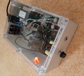
Here is the unit in its case:

More things to do are replacing the rest of the resistors with 1% metal oxide ones and installing an 100kΩ linear potentiometer by Bourns.
Thanks again for your valuable replies and all the interesting info.
- I replaced resistors R7,57 and R14,54 with values 270Ω and 330Ω respectively, as per suggestion by fellow member sgrossklass.
- I added a couple of 100μF electrolytic capacitors in parallel to C13,63, as per suggestion by fellow member sgrossklass.
- I replaced capacitors C7,57 with larger ones: 6μF @100V (ERO 1813).
- I used 4,7Ω resistors in R21,71.
Here is the unit in its case:
More things to do are replacing the rest of the resistors with 1% metal oxide ones and installing an 100kΩ linear potentiometer by Bourns.
Thanks again for your valuable replies and all the interesting info.
Attachments
Should I also change resistors R6, R56 (as of now, they are 100Ω) to match the values of R7, R57 (270Ω)?
The same questions goes for resistors R13, R63 (they also are 100Ω).
Should I change those resistors to match the values of R14, R64 (330Ω)?
Also, could someone explain how the above changes would affect the biasing?
Would it allow for more current?
Forgive my ignorance, but I am here to learn.
The same questions goes for resistors R13, R63 (they also are 100Ω).
Should I change those resistors to match the values of R14, R64 (330Ω)?
Also, could someone explain how the above changes would affect the biasing?
Would it allow for more current?
Forgive my ignorance, but I am here to learn.
Last edited:
Hello Mark,Well the 100k value for the volume pot is rather high - it will probably dominate the noise (not that you have a problem with that). Reworking that network to use 10k might be a good idea (10k pots are easier to source too).
I am using a 10kΩ linear pot right now.
It's fine, but problem is I haven't got a lot of usable range.
The volume gets too loud after 12 'o clock position...
I do not care much for the log behaviour I get by having the resistors R9, R59. If I'd get rid of them (and log behaviour), I'd be quite happy I guess.
Provided I can use a linear potentiometer that would provide me with a usable volume range.
Right now the potentiometer I use is a Bourns 10kΩ linear.
I had this lying there and I tried it.
I can also find the same @ 100kΩ.
So, If there is any mod I can make to just use those linear pots without sacrificing usable volume range i'd be happy.
I note the output bias networks on the NE5534A outputs to move the cross-over point out of use - however the current mirror used (why a mirror anyway?) is only injecting just over 1mA, whereas 5 to 8mA is recommended for minimal distortion on the NE5534A (according to Doug Self). A simple 3k3 resistor to V+ instead of the current mirrors would be simpler and better.
You are not the first to mention that.
I am no expert so I followed sgrossklass advice and substituted R7, R57 and R14, R64 for higher values (from 100Ω to 270Ω/330Ω respectively).
I measured voltage drop across R6, R56, R13, R63 (all 100Ω) and calculated current. It's higher now than it was before (around 2.9mA - 3.1mA).
However, I do not know exactly what I am doing.
In fact I have no clue whether the current of importance (as to class A biasing) is the one across R6.
By the way, If i calculate the current across R7(270Ω), it's still around 1mA.
So much confusion...
- replace the second ne5534 by a modern jfet opamp such as an opa1641.
No DC through the pot, less sensitivity to the varying impedance of the pot.
If you can clarify any appropriate changes needed in order to accommodate for such a swap, I 'd be happy to try it.
I'm no expert so I need help on that.
It would mean:
- soldering opa1641 onto a so8 to dip8 adapter and replace IC2/IC52 with these.
- removing C8/C58.
And that should be it. The opa1641 is unity gain stable and not exceedingly fast so it should be fine at x2.
- soldering opa1641 onto a so8 to dip8 adapter and replace IC2/IC52 with these.
- removing C8/C58.
And that should be it. The opa1641 is unity gain stable and not exceedingly fast so it should be fine at x2.
It would mean:
- soldering opa1641 onto a so8 to dip8 adapter and replace IC2/IC52 with these.
- removing C8/C58.
And that should be it. The opa1641 is unity gain stable and not exceedingly fast so it should be fine at x2.
Thanks.
I'll definitely try it and report back.
By using OPA1641, will I be able to remove R9, R59 without any issues?
Btw, should i use a thin wire to connect the holes of removed capacitors C8, C58?
Or their place can be left just open?
Last edited:
Wrt r9/59: the opa1641 is a jfet input but that doesn't change anything about r9/59. Either you use a 100k linear pot and keep them or you switch to a 10k log pot and remove them.
Wrt c8/58: If you install opa1641 instead of ne5534 and remove c8/c58, leave their positions open. Actually, pins 5 and 8 aren't connected on the opa1641 so you can leave c8/58 installed, they won't do anything. Even easier
Wrt c8/58: If you install opa1641 instead of ne5534 and remove c8/c58, leave their positions open. Actually, pins 5 and 8 aren't connected on the opa1641 so you can leave c8/58 installed, they won't do anything. Even easier
- Status
- This old topic is closed. If you want to reopen this topic, contact a moderator using the "Report Post" button.
- Home
- Amplifiers
- Headphone Systems
- Headphone amplifier "Smart Kit 1215" - possible improvements?