Hugh Dean (AKSA) showed me a pretty cool circuit a few years ago, but it was only recently made public in this thread. It is beautifully elegant with only 2 actives, but worked like a charm. Very useful for making balanced (two identical outputs with 180deg phase) from a single ended input. Orginally, Hugh designed it as a live driver, but I played with the circuit and added a bigger TO220 output transistor and boosted the bias current. What I ended up with was a beautifully simple, elegant and great sounding amp for balanced drive headphones as low as 40ohms impedance. What is nice about this balanced drive circuit is that it doesn't cancel out all the nice second harmonic like many balanced drive circuits - it still has that nice sweet SE Class A profile.
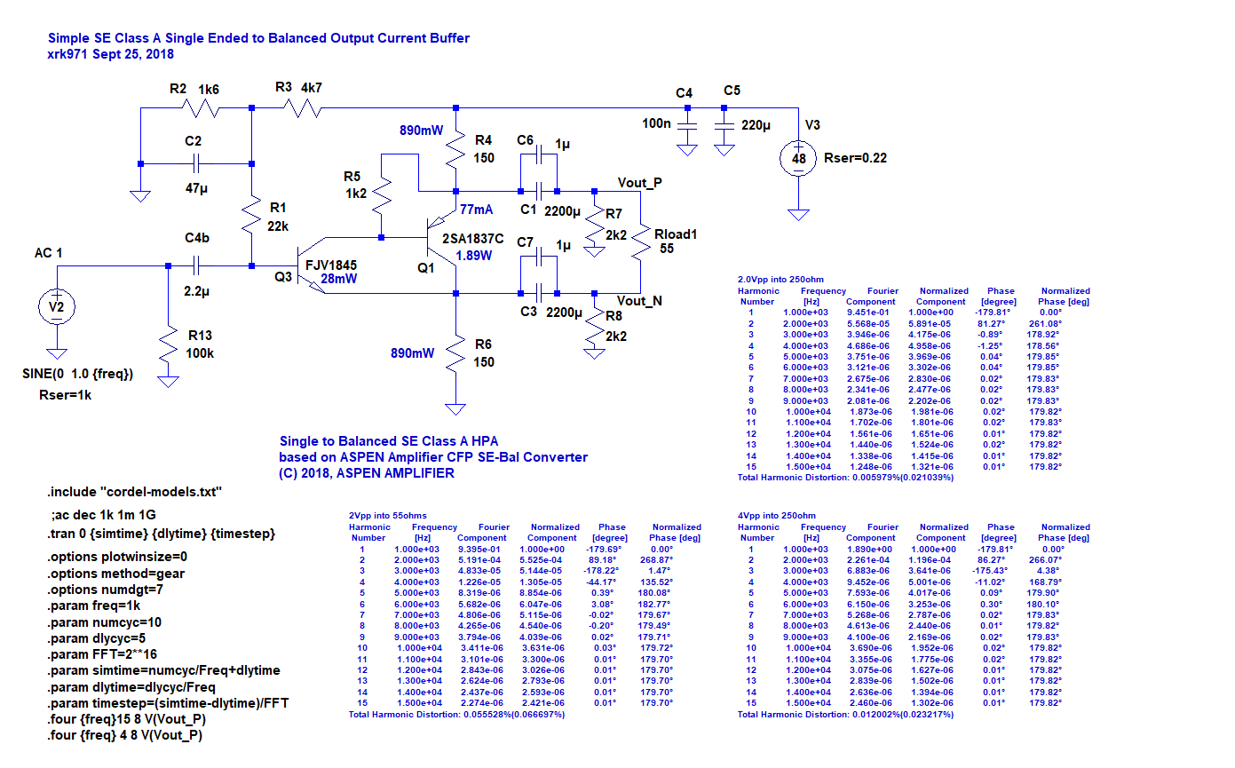
Here is the schematic and some LTSpice performance predictions - predicted THD for 2Vpp into 250ohm cans is 0.006% - a very respectable figure:
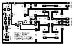
Here is the artwork for a home etched PCB:

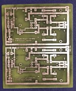
Here is the resulting hand-made etched PCB:

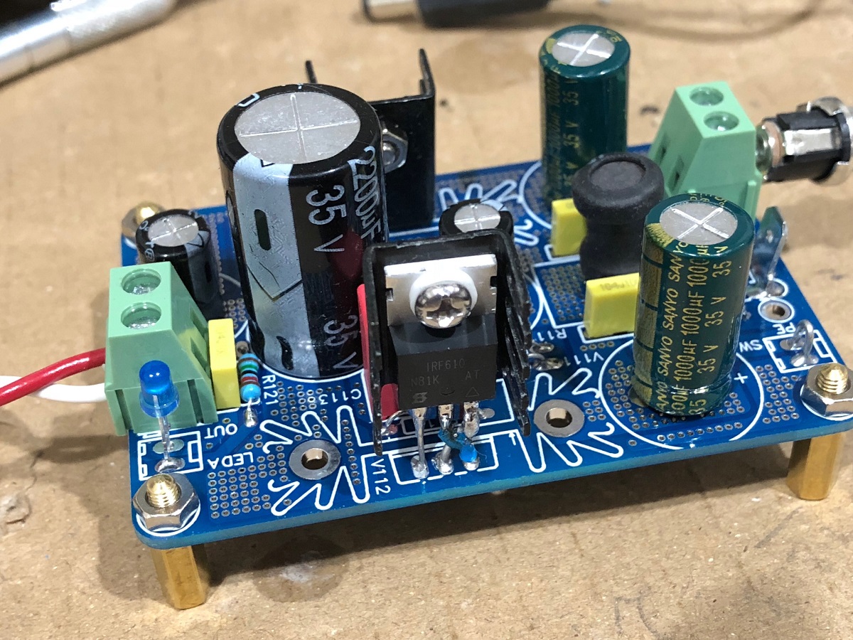
This was the amp that was built - runs off a DC-DC step up from a 12v wall wart, then a simple cap Mx to get 48v rail:
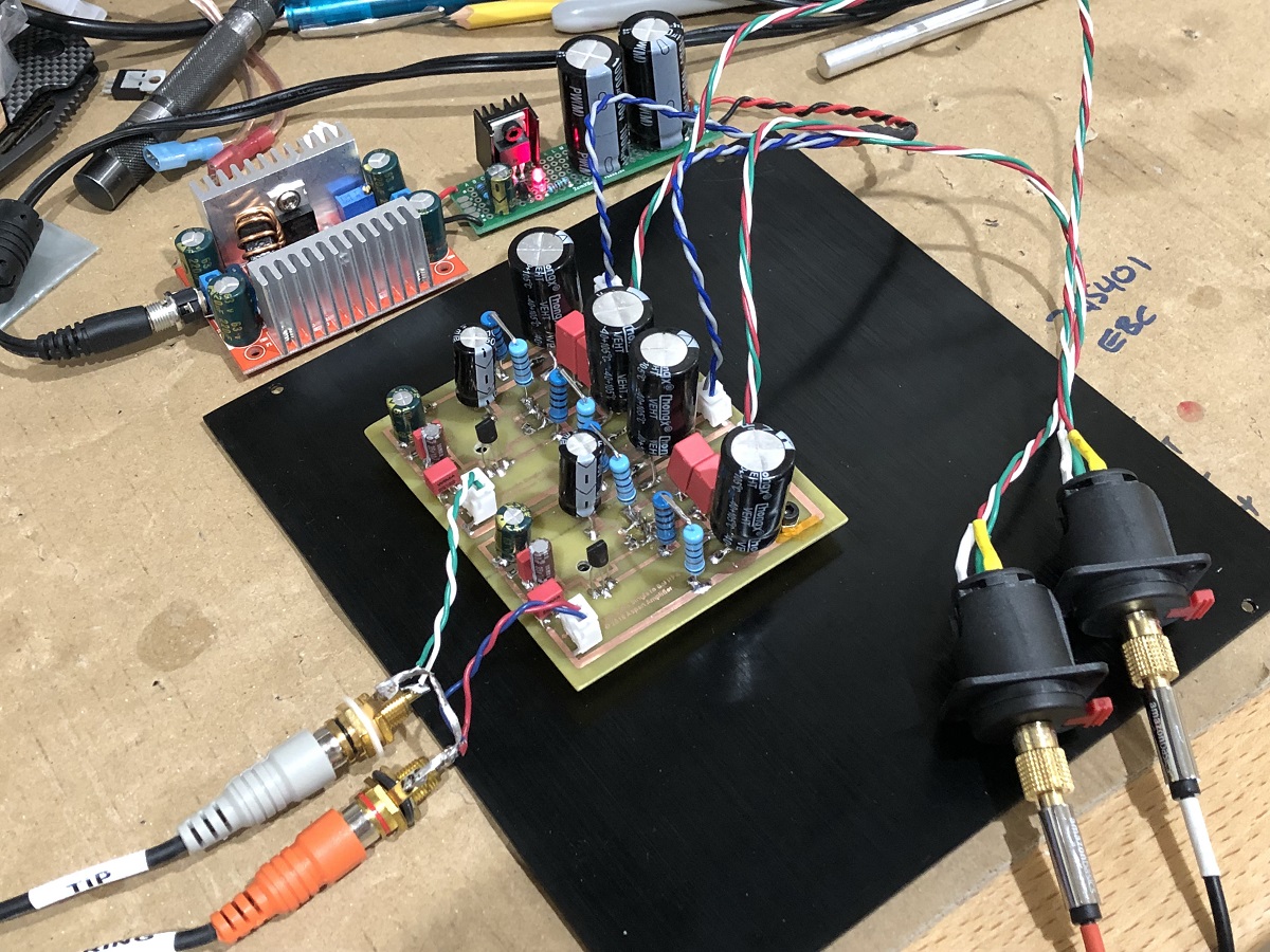
Here is a closeup of the amp:
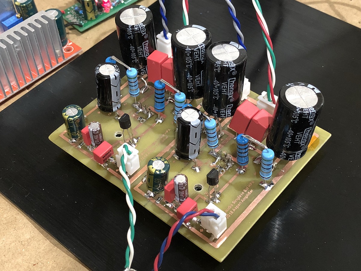
Here is the detail showing the underhung 2SA1837's:

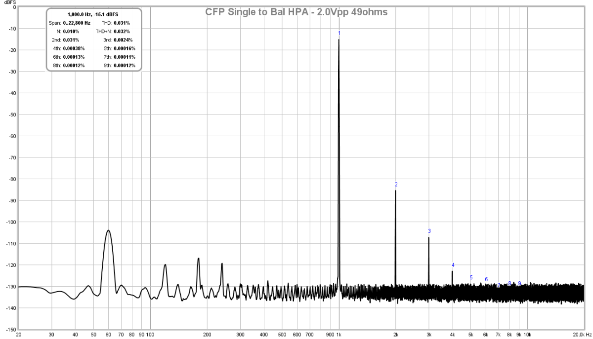
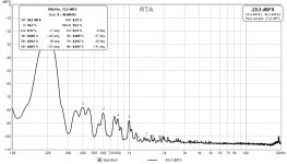
And here is the measured FFT for 2.0Vpp into 49ohms:
How does it sound? Very quiet, very powerful - the dynamics are earth shattering on my OB-1's (rewired for balanced drive). Very nice sounding amp and super easy to make.
Here is the schematic and some LTSpice performance predictions - predicted THD for 2Vpp into 250ohm cans is 0.006% - a very respectable figure:
Here is the artwork for a home etched PCB:
Here is the resulting hand-made etched PCB:
This was the amp that was built - runs off a DC-DC step up from a 12v wall wart, then a simple cap Mx to get 48v rail:
Here is a closeup of the amp:
Here is the detail showing the underhung 2SA1837's:
And here is the measured FFT for 2.0Vpp into 49ohms:
How does it sound? Very quiet, very powerful - the dynamics are earth shattering on my OB-1's (rewired for balanced drive). Very nice sounding amp and super easy to make.
Attachments
Last edited:
Nice work, X. This was quite amazing, the sound quality was remarkable as I recall. Ideal for driving very long leads, particularly in an active system with a large room and heavy lighting. And the distortion profile was terrific, very natural.
Thanks for putting up the circuit. Nico is building one right now to move audio around his home through wires in his roof, which is pretty noisy he tells me.
Hugh
Thanks for putting up the circuit. Nico is building one right now to move audio around his home through wires in his roof, which is pretty noisy he tells me.
Hugh
Per the schematic, 48v. This is achievable using a step up DC-DC converter to 52v then a CLC followed by cap multiplier. This can easily be done using one of these:
GB for Simple Cap-Mx Regulated Low-Noise PSU
Just skip the last voltage regulator with a jumper from pin 1 to 3.
GB for Simple Cap-Mx Regulated Low-Noise PSU
Just skip the last voltage regulator with a jumper from pin 1 to 3.
0.03% THD is not bad for 2 transistors
Correct. And it’s mostly 2nd harmonic and a little 3rd. Beautiful sounding. Very natural and yet very dynamic.
Hugh Dean's 3-Transistor circuit used an emitter follower to drive the base of the output PNP ("Q1" in the schematic of post#1 above). So, in his circuit, the impedance at Q1 base is low, and the impedance at Q1 emitter (=(Zbase/BetaQ1)) is very low. That's the output impedance which drives the top end of the load, node "Vout_p" in the post#1 schematic.
However the 2-Transistor variant in this thread eliminates that emitter follower, and now the base of the output PNP "Q1" is driven by a high impedance: the bootstrapped collector load of NPN transistor "Q3". Bootstrapping the collector load emulates a constant current source, resulting in an extremely high impedance. However, the output impedance which drives the top end of the load, "Vout_p", (Zbase/Beta), becomes a very much larger number. I will hazard a rough guess that the output impedance at "Vout_p" is about (R4 parallel (30*R5/BetaQ1)) = 87 ohms.
When discussing the 3-Transistor circuit, Hugh said
But in the 2-Transistor adaptation of this thread, I am concerned that Zout of the upper output is much greater than 10R. I.e. the balanced output drive now has drastically unbalanced output impedances.
Do you happen to know the Zout of each balanced output in the 2-Transistor circuit?
However the 2-Transistor variant in this thread eliminates that emitter follower, and now the base of the output PNP "Q1" is driven by a high impedance: the bootstrapped collector load of NPN transistor "Q3". Bootstrapping the collector load emulates a constant current source, resulting in an extremely high impedance. However, the output impedance which drives the top end of the load, "Vout_p", (Zbase/Beta), becomes a very much larger number. I will hazard a rough guess that the output impedance at "Vout_p" is about (R4 parallel (30*R5/BetaQ1)) = 87 ohms.
When discussing the 3-Transistor circuit, Hugh said
Zout of each balanced output is around 10R, so this can be used for a 600R balanced line.
But in the 2-Transistor adaptation of this thread, I am concerned that Zout of the upper output is much greater than 10R. I.e. the balanced output drive now has drastically unbalanced output impedances.
Do you happen to know the Zout of each balanced output in the 2-Transistor circuit?
Mark,
I have not tested it with instruments but simulation gives good answers.
The upper output is indeed high impedance but sink and source issues make it unattractive for heavy loads. At 10k it seems just fine.
I believe Zout source is the defined by the collector resistor - 1k on my original design - but the impedance is not so high; it is 1K, the value of the upper resistor on the collector, as expected. Compared to the 26/10=2.6R Zout of the lower output, this is poor, and this is the reason I added an EF to equalise.
The ultimate of this circuit would be an EF on each balanced output, direct connected and cross linked to 10mA CCS on the opposite rail. This then offers identical Zout - 2.6R as suggested - for both outputs. But then we have six transistors, and it's grown up to be come a Cadillac...... with three transistors almost the same performance is available, and indeed Nico Ras tells me has built one with a ceiling twisted pair cable of 30m between two distant rooms of his home and tells me it is outstanding.
I had hoped that by using a cfp I could extract low Zout from both sides, but in truth, it seems only from the lower, with the master emitter end. The upper does have an emitter on the slave, leading me to believe it could also be low, but in truth it is dominated by the master, not the slave, something I should have realised from the operation. But, it might be possible to drop the cfp phase splitter, use only a single device, and place the removed slave into EF duties on both sides.
I doodled a second version with a single transistor in place of the cfp. Both phases are passed directly to BD139/140 EFs using cross linked 2k2 emitter loads from the 15V power supplies (bipolar). With 2k loads for output and 1Vpk input, I saw -113dB H2 and -121dB H3 with 0.00048% at 1KHz. It seems that because the phase splitter, with a high beta transistor (KSC1845), the single current through the stage ensures very good phase splitting, but the Zout imbalance must be redressed with two EFs. This is still a three transistor configuration, and extremely high performing for low parts count. Of course THAT has terrific chips, but it's a nice exercise to do it from first principles.
Thank you for your post.
Hugh
Last edited:
Hugh, thanks for your message. I'm rather pleased that circuit reasoning plus ordinary algebra still gives useful insight, even in an era where "SPICE seems to be all I need!" is the default assumption.
It sounds like you now believe this circuit (the 2T version of this specific discussion thread) ought not be used to drive low impedance loads, say, lower than 1Kohms. Certainly not 600 ohms and absolutely & certainly not "... great sounding amp for balanced drive headphones as low as 40ohms impedance" as mentioned in post #1 above.
It's promising that preliminary investigations show alternative approaches with better performance into low impedance loads. I wonder if the phase splitter were a common-base amplifier (driven by a "Rush cascode"), maybe you could get Really Damn Good performance out of 4 transistors. Two for the phase splitter / Rush cascode, and two more for emitter follower output drivers. Using emitter resistors instead of emitter CCS loads.
MJ
Hi Mark,
Well, I must be a little diffident here. I do not believe that low distortion means good sound, and I don't believe that high distortion means bad sound. Let me explain.
The issue is the nature of the distortion and the coarse nature of the THD figure. My rudimentary topology ensures that if there are imbalances between the two antiphase outputs they will show up as mostly H2, a little H3 and maybe a little H4 too. But we should then examine the human hearing issues and realise that most - not all - but most, like H2/H4 distortion.
So if we produce an amp for headphones which creates musical distortions many people generally like it. This is anaethema to engineers who strive for zero distortion, but this is a belief; the reality is not quite this way, the same way as people like to buy cars entirely on their paint color. XRK and I have done a lot of work in this area of psychoacoustics, and I have done a lot of music in my life (keyboard) that gave me an appreciation of harmonics in the musical scale. We have found that HPA with high levels of H2 and all subsequent harmonics dropping linearly (monotonic decrease a la Hiraga) the sound seems 'natural'. Absurdly subjective, and therefore easy to ignore, and lots of good engineers do just that. But if you create H2 at -75dB, H3 -90dB H4 -105dB and H5 -120dB the sound quality seems to be very natural, slightly sweet, and engaging. These issues are not easily measurable, but recent digital developments (focusRite) gives us the way to do it cheaply now. Tube aficionados know this effect well. I built an amp with tubes 25 years ago with H2 at -45dB. It did not sound wooly at all; it was entrancing, and people really liked it, even with orchestras. That was a 6SL7 operating at B+ 340V and 1.6mA and 100k plate load. The remainder of the circuit was zero distortion, all SS with feedback. The amp had high distortion, yet it sounded just wonderful.
This set me on the path of psychoacoustics. I take note of THD, but I try to examine the individual harmonics and their relationships. XRK has helped me hugely to measure and produce better amplifiers which people like to listen to for hours on end.
Nothing of this is new. It's been there for sixty years. Linsley Hood and Jean Hiraga in the sixties knew about it and Nelson Pass is well acquainted with it over the last forty years. But opposing ideologies about the engineering and marketing strategies have obfuscated the issues. I might be completely wrong, but I don't think so. But to prove this with academic rigor some careful testing needs to be done, with real money, and then someone has to take on the market machine which dominates the audiophile world. Remember the Japanese wars of THD in the eighties? WOW, some dreadful amps came out of that.......
Hugh
xrk971 , the legendary class A man is back.
By the way , I am a electric guitar player , too be honest certain types of noise actually fills good . I have a modern class AB amp , which I don't hate but old germanium based Class A amp which I got from my granny sounds really amazing as if I am listening to some short of tube amp .
We shall remember that sound is subjective so only objective measuring can't explain whether a AMP sound's good or not . Probably you guys know guitar player generally prefers germanium fuzz pedal over silicon one .
Last edited:
Hmm, ok, so the math is wrong (Zout of each balanced output is 10R) but nevertheless the sound is right (?). Then why even mention the math? It only distracts from the main message which, apparently, is: forget numbers, they do not match human perception.
What has happened here is, somebody focused upon SPICE simulated harmonic distortion without checking whether the balanced outputs were or were not balanced. Upon discovery that in fact they are not balanced, not even close, the goalposts begin to move. Ok.
What has happened here is, somebody focused upon SPICE simulated harmonic distortion without checking whether the balanced outputs were or were not balanced. Upon discovery that in fact they are not balanced, not even close, the goalposts begin to move. Ok.
I would worry less about thd or absolute balance (which doesn't matter much for headphones) than about the effect on frequency response of a highish output impedance into headphones. Some have a very uneven impedance curve.
Once you get through the trouble of having a pcb made, adding a few transistors into the mix is a very marginal effort/cost. So those EF mentioned sounds like a good idea to me.
Once you get through the trouble of having a pcb made, adding a few transistors into the mix is a very marginal effort/cost. So those EF mentioned sounds like a good idea to me.
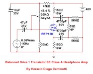
Horacio, take a close look at the "balance" of the 1-MOSFET circuit you posted. The output impedance of the top node (drain) is 150 ohms, while the output impedance of the bottom node (source) is [150 || (1/gm)] where "gm" is the transconductance of the MOSFET at the chosen bias current. I assume you'll bias it somewhere around 77mA , similar to the schematic in post #1. The impedances are not even close to balanced.
Possibly, I should change the name of my circuit from balanced to unbalanced, or better yet, to floating  . I should change the name of my circuit from amplifier to buffer, too . If someone tests it, you will find that it does not respond very differently to the one that starts this thread.
. I should change the name of my circuit from amplifier to buffer, too . If someone tests it, you will find that it does not respond very differently to the one that starts this thread.In relation to the objective of reaching superlative parameters in the design of a stage of the sound chain, I have found a certain contradiction. This contradiction could occur when the possible response of the transducer is not integrated in its way of altering the waves that finally reach our ears, in the design objectives for the favorable treatment of electrical signals.
There are clear guidelines that should be achieved, regardless of how the transducer responds acoustically: how, for example, to avoid zero crossing distortion of the electrical signal, among some other possible ones.
An electrodynamic transducer can reach a noticeable rate of acoustic distortion, much higher in value than the rates of electrical distortion of today's designs.
With very simple measurements, one can easily find that the acoustic distortion of a transducer could reach values of 2 to 3% in determined frequency and level of excitation, while that of an amplifier itself (for example) could be placed several orders of magnitude below , for the frequency and levels that the same transducer needs simultaneously with the previously mentioned values.
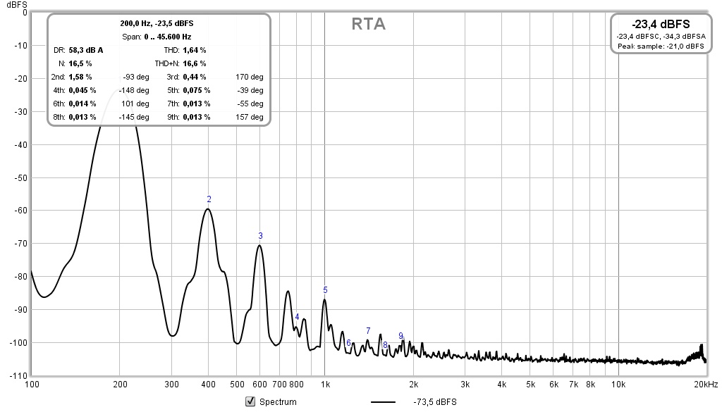
I have measured the distortion of a transducer fed with a practically pure fixed frequency sinewave signal. While the electrical signal had a distortion of 0.00031%, the acoustic distortion reached values of 1.64%.
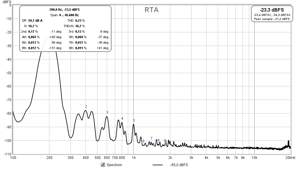
Then, I altered the distortion composition of the electrical signal to achieve a lower value of acoustic distortion in the transducer. The amplitude and fundamental frequency of the electrical signal was maintained, but its electrical distortion increased to no less than 2.66%, to reduce that produced by the transducer to only 0.23% !!!.

It does not necessarily imply that maintaining that same composition and level of electrical distortion at other frequencies, there will always be a reduction of the acoustic distortion in the transducer (since its composition also varies frequency to frequency and with the different levels applied). In fact, I have measured the acoustic distortion at other frequencies, applying a similar fundamental amplitude of electric signal and similar spectral composition ratio (THD of 2.66%) and the acoustic distortion would seem to be reduced only in a limited frequency range, although in other ranges it could even be greater than that obtained with an almost pure electrical signal.
The point is to try to minimize acoustic distortion in zones of sensitive frequencies and amplitudes of the audible range, while possible increases in acoustic distortion can occur in less sensitive areas of the spectrum and level.
Something interesting to know is that electrodynamic transducers show spectral compositions with appreciable levels within the first components such as H2, H3 and, perhaps, some of the H4, provided that it is operated within its most linear area of operation. Interestingly, the spectral composition of the electrical signal that could minimize acoustic distortion in the transducer contains almost the same spectral components (H2 and H3 or, at most, H2, H3 and some H4). That electric distortion profile could correspond to the typical of a single ended operating circuit.
Best regards
There are clear guidelines that should be achieved, regardless of how the transducer responds acoustically: how, for example, to avoid zero crossing distortion of the electrical signal, among some other possible ones.
An electrodynamic transducer can reach a noticeable rate of acoustic distortion, much higher in value than the rates of electrical distortion of today's designs.
With very simple measurements, one can easily find that the acoustic distortion of a transducer could reach values of 2 to 3% in determined frequency and level of excitation, while that of an amplifier itself (for example) could be placed several orders of magnitude below , for the frequency and levels that the same transducer needs simultaneously with the previously mentioned values.
I have measured the distortion of a transducer fed with a practically pure fixed frequency sinewave signal. While the electrical signal had a distortion of 0.00031%, the acoustic distortion reached values of 1.64%.
Then, I altered the distortion composition of the electrical signal to achieve a lower value of acoustic distortion in the transducer. The amplitude and fundamental frequency of the electrical signal was maintained, but its electrical distortion increased to no less than 2.66%, to reduce that produced by the transducer to only 0.23% !!!.
It does not necessarily imply that maintaining that same composition and level of electrical distortion at other frequencies, there will always be a reduction of the acoustic distortion in the transducer (since its composition also varies frequency to frequency and with the different levels applied). In fact, I have measured the acoustic distortion at other frequencies, applying a similar fundamental amplitude of electric signal and similar spectral composition ratio (THD of 2.66%) and the acoustic distortion would seem to be reduced only in a limited frequency range, although in other ranges it could even be greater than that obtained with an almost pure electrical signal.
The point is to try to minimize acoustic distortion in zones of sensitive frequencies and amplitudes of the audible range, while possible increases in acoustic distortion can occur in less sensitive areas of the spectrum and level.
Something interesting to know is that electrodynamic transducers show spectral compositions with appreciable levels within the first components such as H2, H3 and, perhaps, some of the H4, provided that it is operated within its most linear area of operation. Interestingly, the spectral composition of the electrical signal that could minimize acoustic distortion in the transducer contains almost the same spectral components (H2 and H3 or, at most, H2, H3 and some H4). That electric distortion profile could correspond to the typical of a single ended operating circuit.
Best regards
Attachments
Last edited:
Horacio, take a close look at the "balance" of the 1-MOSFET circuit you posted. The output impedance of the top node (drain) is 150 ohms, while the output impedance of the bottom node (source) is [150 || (1/gm)] where "gm" is the transconductance of the MOSFET at the chosen bias current. I assume you'll bias it somewhere around 77mA , similar to the schematic in post #1. The impedances are not even close to balanced.
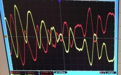
You know Mark, you don’t need perfectly balanced impedance on the two halves to have pretty darn good balanced output signals as anyone can see from this OScope screenshot. Also, the slight imbalance imparts a more pleasing second harmonic signature as shown in the FFT.
Attachments
- Status
- This old topic is closed. If you want to reopen this topic, contact a moderator using the "Report Post" button.
- Home
- Amplifiers
- Headphone Systems
- Balanced Drive 2 Transistor SE Class A Headphone Amp