Excellent work xrk971 !!!
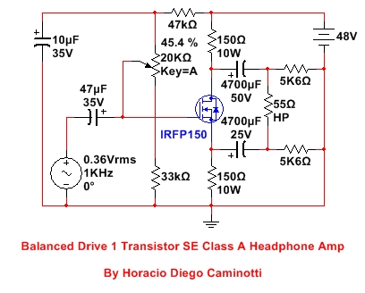
Why not try it with just one transistor? I think it can be equally as good as the first, only using a somewhat less components and perhaps more compact.
Best regards
Nice work Diegommj!
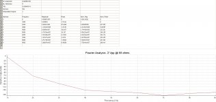
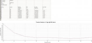
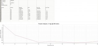
Very cool to see it done with only 1 transistor - what does the predicted FFT look like? I’m sure it’s H2 dominant as well.
Cheers,
X
To say it again: those circuits are neither good headphones amps as output impedance is too high, nor good balanced line drivers as they aren't impedance balanced.
As an aside, "balanced" is of no benefit whatsoever for headphones. It's a misunderstanding that started on headfi a long long time ago when some amps were bridged to increase power and never went away because it made for great marketing.
As an aside, "balanced" is of no benefit whatsoever for headphones. It's a misunderstanding that started on headfi a long long time ago when some amps were bridged to increase power and never went away because it made for great marketing.
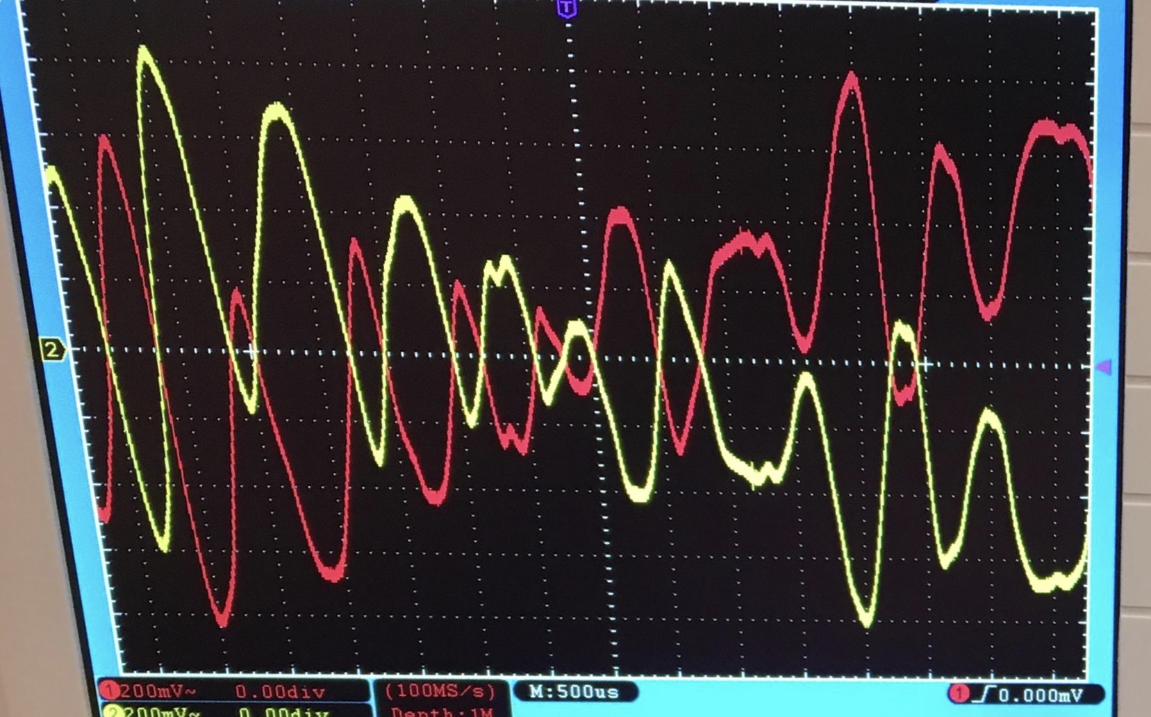
They work quite well and sound great as headphone amps. Have you even listened to one? Probably not, output impedance is not everything on a headphone amp. And again, to say it doesn’t work well as a line driver? Once again, just look at the traces - mirror image copies. I find it annoying that people want to “warn” others of trying something so simple that sounds and works well, purely because they have hard set ideas that certain things must be adhered to like perfectly balanced impedance on on both sides. Heck, add a series resistor on one side to balance it to 600ohms even if you have to.
I've listened to plenty of headphones amps with a variable resistor at the output (or amps with a natural highish output impedance, as you often get with OTL tubes amp). A higher output impedance can sound "nice" but it's definitely not accurate.
As for balanced output impedance, it matters more in line drivers than signal balance. Those scope traces don't tell an useful story. Yeah, they look nice. But how are they useful ?
As for balanced output impedance, it matters more in line drivers than signal balance. Those scope traces don't tell an useful story. Yeah, they look nice. But how are they useful ?
Nice work Diegommj!
Very cool to see it done with only 1 transistor - what does the predicted FFT look like? I’m sure it’s H2 dominant as well.
Cheers,
X
Thanks X!!!
You are right, X, the H2 is dominant. Very similar to your circuit.
Cheers
Attachments
- Status
- This old topic is closed. If you want to reopen this topic, contact a moderator using the "Report Post" button.
- Home
- Amplifiers
- Headphone Systems
- Balanced Drive 2 Transistor SE Class A Headphone Amp