Suresh, there is no LTSPICE simulation file for T2 that I am aware of. It might not be an easy job to create one; for example, component D25 is made by a small company in Japan and they appear not to provide .MODEL parameters of their devices. So you'll need to create your own simulation model of D25. Probably that means extracting its Current vs Voltage transfer characteristic on a curve tracer. Whether the remaining components are already modeled in LTSPICE or not, I don't know. Good luck!
Just for fun -
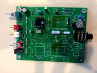
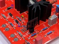
Here's a photo of the first T2 prototype; you can see that a lot has changed between then and now. Most noticeable perhaps is the early use of two metal oxide resistors (baby blue Panasonics) rather than today's cluster of four metal film resistors (brown Vishays). Those resistors in the prototype ran very VERY hot.
The early heatsinks were lay-down types; today's are oriented vertically, with much deeper radiator fins. You can see the Kapton tape I put on the PCB, to prevent short circuits between top copper and heatsink. I bent up the TO-220 and removed its heatsink on this PCB, you can still see the white heatsink thermal paste on the tab side of the transistor.
Lots of changes were made to the power supply section; to name one example, the prototype used four discrete diodes in the oddball SOD-57 spherical package. You'll probably notice others.
The prototype used a small and cheap RK097 potentiometer; this has been changed to an ALPS Blue Velvet RK27 in the current BOM.
_
Attachments
Shootout: Whammy vs T2
I just completed a Whammy, so of course, I had to do another headphone amp shoot out (admittedly subjective and probably biased I ways I don't even understand myself). Here's an excerpt from my post in the Whammy forum:
"..... My two other HP amps are Pete Millett's NuHybrid and Mark Johnson's T2, both of which have SMPS regulated supplies. All 3 sound different. Not earth shaking but with discernible differences.
Wayne's amp is the most well behaved circuit of the 3. Dead quiet, no turn on or turn off noises, gobs of gain. If there are any drawbacks for me, it is that the bass seems a bit soft compared to the other two, perhaps that is a characteristic of the power supply, maybe the opamp.
The other thing is that the Whammy sound character is pretty obviously driven by the choice of the front end opamp. Mark's T2 beats the Whammy in that respect in that the T2 really doesn't have much of a front end. Also, not enough gain to adequately drive low sensitivity planar magnetic headphones.
So, my initial response is, the Whammy is very quiet, has good gain, is very detailed and would make a good studio monitoring headphone amp but it is not as exciting as either the NuHybrid or even the T2. The NuHybrid ended up the most costly of the 3 because I found I prefer listening to the source in its original polarity, which required some expensive Jensen input transformers, reversed to compensate for the triode circuit inversion inherent in the design.
For a first time builder, I would recommend Mark's T2. Easier to build, less expensive, and more fun to listen to, as long as you don't need a ton of gain."
Thanks for posting this, I'll add your post# it to the "How does it sound" list.
Just for fun, some day you may decide to try T2 + planar magnetic headphones + a different source with higher output. T2's voltage gain is low (+6dB), but it pumps out gobs of current -- maybe you'll discover it makes beautiful music with the planar magnetic 'phones, when the source voltage is adequately high. Or maybe it defecates the bedsheets; experiment and discover.
Just for fun, some day you may decide to try T2 + planar magnetic headphones + a different source with higher output. T2's voltage gain is low (+6dB), but it pumps out gobs of current -- maybe you'll discover it makes beautiful music with the planar magnetic 'phones, when the source voltage is adequately high. Or maybe it defecates the bedsheets; experiment and discover.
Thanks for posting this, I'll add your post# it to the "How does it sound" list.
Just for fun, some day you may decide to try T2 + planar magnetic headphones + a different source with higher output. T2's voltage gain is low (+6dB), but it pumps out gobs of current -- maybe you'll discover it makes beautiful music with the planar magnetic 'phones, when the source voltage is adequately high. Or maybe it defecates the bedsheets; experiment and discover.
Mark:
Any pros/cons thoughts on adjusting the gain up a bit by changing R75/R76 to 47 ohms and R77/R78 to 91 ohms?
I think I'm going in the correct direction here but I'm dyslexic, so maybe I have it backwards. If not, it seems 150 mA of bias would be set as 6.82 volts of drop across R77.
Sure, go ahead and mess around with T2 if you wish. Because T2 is AC coupled at both the input and at the output, you can't hurt other equipment even if you accidentally do something disastrously wrong inside the T2 circuit. It's your board, feel free to install your ideas upon it.
The circuit gain is [(R77 || R78) + (R75 || R76)] / (R75 || R76)
and, no surprise, changing the resistor values changes the gain. To maintain 150mA of bias current in the Nchannel MOSFET, you need to have 75mA flowing in R77 and another 75mA flowing in R78. Thus
Voltage_across_R77 = 0.075_amps x R77_in_Ohms
Try it when R77 = 68 ohms; the formula says Voltage_across_R77 = (0.075 x 68) = 5.1 volts. Eureka.
You also probably want to increase the adjustment range of the bias trim circuit, so it will be able to deal with your modified resistor network. You could either cut R72 in half (to 75K ohms), or double the trimmer R73 (to 500K ohms).
Finally, notice that your new resistor values mean that two of the resistors will run cooler than before, and two of the resistors will run hotter than before. Same current, different resistance ---> different dissipation. Somebody's gonna be EVEN HOTTER than she used to be.
_
Attachments
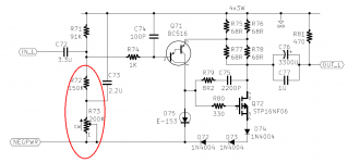
Neat little amp that I've been meaning to comment on for a while... even if the claim of 2 transistors is in fact rather dubious (a Darlington is a Darlington, and a CRD is a JFET current source). I happened to be wondering whether bypassing the three diodes would be beneficial (as their dynamic resistance would provide nonlinear degeneration for the MOSFET), so I grabbed the models posted earlier, made symbols for them and got everything to work.
Turns out there is in fact a significant increase in loop gain and corresponding reduction in distortion with the extra bypass cap - about 14 dB in sim. If you've got some low-voltage (6.3-10 V) electrolytics of several thousand µF floating around, this seems well worth a shot. These actually aren't super huge, a 4700µ/6.3 Panasonic FC is 12.5x30 or 16x20 mm (DxL). Remaining stock from motherboard recapping projects (often 3300µ/6.3V) should also work well.
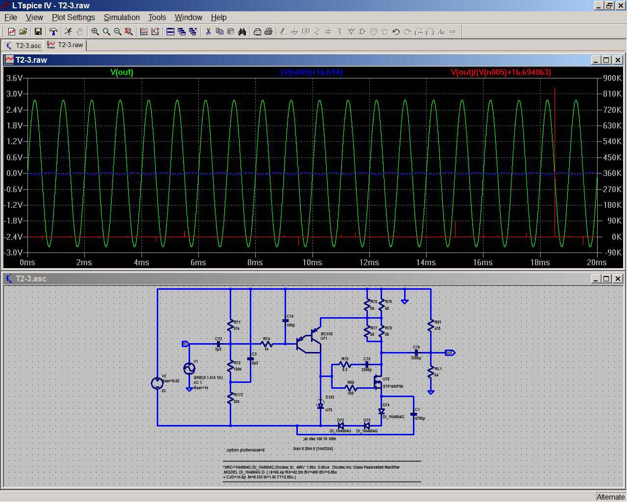
Turns out there is in fact a significant increase in loop gain and corresponding reduction in distortion with the extra bypass cap - about 14 dB in sim. If you've got some low-voltage (6.3-10 V) electrolytics of several thousand µF floating around, this seems well worth a shot. These actually aren't super huge, a 4700µ/6.3 Panasonic FC is 12.5x30 or 16x20 mm (DxL). Remaining stock from motherboard recapping projects (often 3300µ/6.3V) should also work well.
Attachments
Last edited:
Correction:
There in fact is essentially no increase in loop gain - this is purely a large-signal effect. Plot diode current and you'll see why the bypassing helps.Turns out there is in fact a significant increase in loop gain and corresponding reduction in distortion with the extra bypass cap
Attachments
Last edited:
I think I might put two of these in my Mouser shopping cart, waiting for the next time I order.
Axial, in stock, 4700uF , 16V , 1.84A ripple current , 16mm x 31mm
478TTA016M Illinois Capacitor / CDE | Mouser
Axial, in stock, 4700uF , 16V , 1.84A ripple current , 16mm x 31mm
478TTA016M Illinois Capacitor / CDE | Mouser
If the Vgs of Q22 and Q72 at operating temp and Id is circa 4 volts, or at least more than 3 volts when warm, then there is an alternative CCS for that 15mA that will allow the removal of those diodes altogether. I'll be trying a three terminal LED, npn and two resistor CCS when my board arrives. Will need to check for DC stability. Will still call it a T2 though.
BTW Mark, my boards have just spent their last week in Canada before working their way back to San Francisco. Nice little sightseeing tour courtesy of USPS!
BTW Mark, my boards have just spent their last week in Canada before working their way back to San Francisco. Nice little sightseeing tour courtesy of USPS!
Spend a little time with your DVM set to continuity buzzer, mapping out the weirdness on the PCB in the vicinity of D75. As my Arkansas buddies say, "you might could use that."I'll be trying a three terminal LED, npn and two resistor CCS when my board arrives. Will need to check for DC stability. Will still call it a T2 though.
It's OK Mark but many thanks for the kind offer. I've just now had two messages from USPS saying they have left San Francisco to their destination country. Second time lucky I hope. To be honest I will not have the time to build the boards up until next week anyway now so no great loss. Not one bit your fault of course.
John
John
Spend a little time with your DVM set to continuity buzzer, mapping out the weirdness on the PCB in the vicinity of D75. As my Arkansas buddies say, "you might could use that."
Yeah, I did see quite a few mystery pads in that area that could come in handy. Did you plan for something like this?
What's on the board is an array of test points (both layers) and nodal access holes, put there to help diagnose weird problems that might conceivably arise when you mix a bipolar, a current source, and a MOSFET together at the same circuit node. But I think if you spend 40 minutes doing continuity buzz-checks & discovering which copper donuts are close together and where they go, you just might find these PCB structures, ahem, utile for your proposed modification. Only a guess, no guarantees.
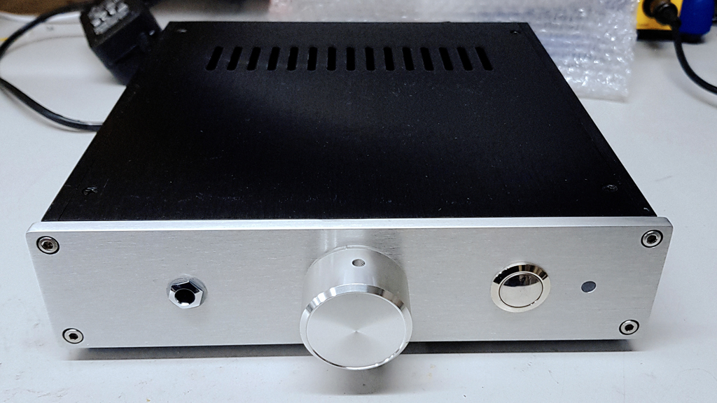
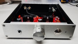
Chassis arrived ")
I went for a clean, simple look with this one. Flush mount bi-colour LED which happens to turn on red (I went for the lucky-dip selection process).

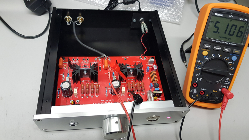
Biasing the amp. Probably close enough to 5.10v. Bias is pretty stable with just a little wander of around 0.15v during warm-up.
Bags of room in the chassis to later convert to a linear supply or perhaps integrate a RaspPi media player.
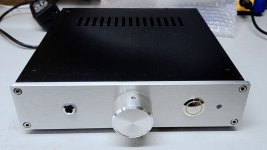
Closed up chassis. I actually turned the top cover to have the vents directly above the load resistors. Also shows off the pretty insides
Listening to this amp right now and it is dead quiet with no input and cranked to 11. I'm not good with cliche but I'll say that the music seems to be unmolested, and detailed. It doesn't sound muted or muffled in any way. Balanced well, the treble is clear but doesn't stand out annoyingly. Bass end is as good as my headphones will produce.
In summary, a very nice, easy to build headphone amp that sounds great - perfect for someone starting out with DIY or as an enjoyable side project for the more experienced builder. Everything went together as documented, even with BOM substitutions due to local supply issues.
Thanks Mark!
I went for a clean, simple look with this one. Flush mount bi-colour LED which happens to turn on red (I went for the lucky-dip selection process).
Biasing the amp. Probably close enough to 5.10v. Bias is pretty stable with just a little wander of around 0.15v during warm-up.
Bags of room in the chassis to later convert to a linear supply or perhaps integrate a RaspPi media player.
Closed up chassis. I actually turned the top cover to have the vents directly above the load resistors. Also shows off the pretty insides
Listening to this amp right now and it is dead quiet with no input and cranked to 11. I'm not good with cliche but I'll say that the music seems to be unmolested, and detailed. It doesn't sound muted or muffled in any way. Balanced well, the treble is clear but doesn't stand out annoyingly. Bass end is as good as my headphones will produce.
In summary, a very nice, easy to build headphone amp that sounds great - perfect for someone starting out with DIY or as an enjoyable side project for the more experienced builder. Everything went together as documented, even with BOM substitutions due to local supply issues.
Thanks Mark!
Attachments

- Status
- Not open for further replies.
- Home
- Amplifiers
- Headphone Systems
- Single ended class-A headphone amp using two transistors: T2