...there are two #8 solder lugs in the BOM, what or where are these used for?
Hi, please see pages 22 and 23 of the T2 build notes pdf files for photographs and explanations. The lugs help ensure that all six panels of the chassis are solidly connected together in a Faraday cage, to block hum.
Stainless Steel M4 socket cap bolts for PCB front/rear panel mounting
The 1U Galaxy chassis from the diyAudio Store, ships with metal front and rear panels that mount to the rest of the chassis using countersunk screws. And the hardware kit that comes with the chassis, includes flat head screws with tapered sides that fit perfectly into the countersunk holes.
However, the PCB fab does not offer the option of drilling holes in the PCB material with countersinking. So if you attempt to attach the PCB material front and rear panels with the presupplied flat head screws, the screw heads won't be perfectly flush. The tapered sides of the bolt heads aren't aligned with un-countersunk holes. This may or may not be a bother to you.
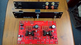
I decided that I liked the color contrast of stainless steel "cap screws" to hold the black front and rear panels in place. You can see these in the photos attached to post #1 and #2. If anyone is wondering where I got them and how much I paid, the answer is: amazon.com. They are M4 x 10 mm stainless steel cap screw bolts with hex sockets.
Amazon.com: uxcell M4x10mm Thread 304 Stainless Steel Hex Socket Head Cap Screw Bolt DIN912 120pcs: Home Improvement
The 1U Galaxy chassis from the diyAudio Store, ships with metal front and rear panels that mount to the rest of the chassis using countersunk screws. And the hardware kit that comes with the chassis, includes flat head screws with tapered sides that fit perfectly into the countersunk holes.
However, the PCB fab does not offer the option of drilling holes in the PCB material with countersinking. So if you attempt to attach the PCB material front and rear panels with the presupplied flat head screws, the screw heads won't be perfectly flush. The tapered sides of the bolt heads aren't aligned with un-countersunk holes. This may or may not be a bother to you.
I decided that I liked the color contrast of stainless steel "cap screws" to hold the black front and rear panels in place. You can see these in the photos attached to post #1 and #2. If anyone is wondering where I got them and how much I paid, the answer is: amazon.com. They are M4 x 10 mm stainless steel cap screw bolts with hex sockets.
Amazon.com: uxcell M4x10mm Thread 304 Stainless Steel Hex Socket Head Cap Screw Bolt DIN912 120pcs: Home Improvement
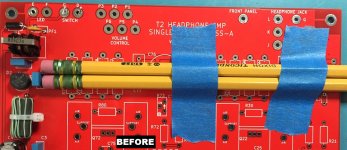
Here's what member adydula is talking about.
Notice the mistake in the before picture!!
The green metal barrel which holds the eraser is round, not hexagonal, and it's slightly larger diameter than the wooden hexagonal pencil. So after soldering the pencils will slide left but they won't slide right: resistor #2 (resting on wood) is too low and the metal barrel won't slide below it.
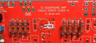
Solution #1 (good): before soldering, arrange the pencils with their eraser ends on the right, where they are not blocked by the power supply components. Now after soldering the pencils slide out effortlessly, to the right.
Solution #2 (ugly): after soldering, use great big diagonal cutting pliers to cut the left ends of the pencils off. You may need two "bites" to chomp off all of the green metal barrel. Now slide the amputee pencil stubs to the right.
_
Notice the mistake in the before picture!!
The green metal barrel which holds the eraser is round, not hexagonal, and it's slightly larger diameter than the wooden hexagonal pencil. So after soldering the pencils will slide left but they won't slide right: resistor #2 (resting on wood) is too low and the metal barrel won't slide below it.
Solution #1 (good): before soldering, arrange the pencils with their eraser ends on the right, where they are not blocked by the power supply components. Now after soldering the pencils slide out effortlessly, to the right.
Solution #2 (ugly): after soldering, use great big diagonal cutting pliers to cut the left ends of the pencils off. You may need two "bites" to chomp off all of the green metal barrel. Now slide the amputee pencil stubs to the right.
_
Attachments
Yes it appears that somehow the BOM calls for 100 ohm resistors in positions R30 and R80 when in fact we want 330 ohm resistors there! Ouch! I apologize for the mistake.
Those are MOSFET "gate stoppers" (oscillation preventers) and they dissipate zero DC power, so any 330 ohm resistor that fits the footprint and has a power rating greater than 1/8th Watt would be okay.
If you don't have 330 ohm resistors in your junk box, 270 ohms or 300 ohms would work too.
I will work with 6L6 to correct the BOM and the Mouser shopping cart!
I recommend that T2 builders affix a label on their 24VDC wall wart, which says
T2 HEADPHONE AMPLIFIER
and then always double check to be sure the only wall wart you ever plug in to your T2, is this one. Its mate. Your dedicated T2 wall wart. Me, I have dedicated one specific Triad WSU240-750 wall wart (the one in the BOM) for my T2, and I have labeled it so there's no confusion.
If you accidentally or deliberately swap different wall warts into your T2, you're going to get different amounts of Class-A bias current each time. You don't want that, nobody wants that. Stick with one and only one wall wart, set the bias current on T2 using this one, and don't plug any other warts into your T2, ever. That's my recommendation.

Sure, it's DIY! Build it however you wish! T2 requires a floating 24VDC input of 500 mA or more, since it is designed with a wall wart in mind. Neither V+out nor V-out of the power supply should be connected to any sort of ground and particularly, not to Protective Earth. The PSU spec sheet will say something like "Isolation: 3KV from output to PE".
Just for simplicity of debug and test, you may want to spend $11.55 and buy the wall wart anyway. So you don't need to assemble and wire up the second chassis before initial power-on and troubleshooting.
Just for simplicity of debug and test, you may want to spend $11.55 and buy the wall wart anyway. So you don't need to assemble and wire up the second chassis before initial power-on and troubleshooting.
Having the wall wart will also let you perform Before vs. After tests, to find out whether or not the sound of the T2 changes when you switch from one supply to the other. Huge difference? Small difference? No difference at all? You will know the answer with certainty.
That's the fun of DIY!!!!
Hello...
Ok, most all parts installed, just need to get the 28ga wire for the ferrite bead, should be here tomorrow, thanks AGDR for the Amazon source. The case came to day but I was out and missed the Fedex man, should be here tomorrow as well.
Then wire up, test and install...set the pots and hopefully listen and watch the heat boil off those big resistors!
:>)
Alex
Attachments
FYI I harvested some high quality AWG-28 stranded wire from thin Ethernet CAT-6 cable, specifically this one at amazon
Notice that it says 28 gauge wire in the specifications section. I also bought a ten-pack of assorted color AWG28 solid core wire from Remington, as mentioned in post #15 above.
The narrow, 4 inch long zip ties were part of an assortment which I bought at Amazon. Or if you don't want an assortment you can just buy the 4-inch ones all by themselves
Amazon.com: AUSTOR 600 Pieces Zip Ties White Nylon Cable Zip Ties Heavy Duty Industrial Grade Wire Ties Cable Ties in 4 6 8 10 Inches for Home Office Garage and Workshop(Each Size 150 Pcs): Home Audio & Theater
Amazon.com: SE CT4N 4" White Cable Ties with 18-lb. Tensile Strength (100 Count): Home Improvement
Amazon.com: SE CT4N 4" White Cable Ties with 18-lb. Tensile Strength (100 Count): Home Improvement
- Status
- Not open for further replies.
- Home
- Amplifiers
- Headphone Systems
- Single ended class-A headphone amp using two transistors: T2