You are never going to hear a bass reduction, even if you used 4.7µF.OBTW...I did use a 4700uf cap to bypass the diodes and dont hear any real bass reduction?
The only effect is an increase in THD at low frequencies.
Since the 1/gm of the MOS at this current is ~0.5Ω, for the correction to extend down to 20Hz, you would need 16,000µF.
Not very practical, but there might be solid polymer, 2.5V caps reaching that kind of value in a reasonable size.
Since the THD is in majority caused by the diodes, replacing them with a 17Ω resistor could be an option
Unnecessary: use a low-leakage type (all modern types are), it will be sufficientStill would like an opinion on using a non polorized electrolytic for the bypass "remove" the turn on thump solution?
23 V I think, at least that's what I used in sim.How does this fare as a preamp ?
what is dc voltage that the circuit sees after all the filtering ?
It would do OK as a preamp, but is really not optimized for the application. You could do better with less (parts cost and power consumption).
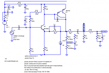
I would rather suggest something more akin to this:
It's inspired in part by the Radford ZD22 and uses the Darlington and CRD from the T2, but towards the output side this time.
Simulation says less than 0.001% of THD @ 1 kHz, 1.5 Vrms with a 10 kOhm load, more like 0.0003% with 50 kOhms. (As usual, keep your salt shaker handy.) Gain ~16.4 dB. Effective input noise will vary a bit depending on whose BC550 you get, the ones Bob Cordell modeled (Rbb' = 170 ohms) would yield about 3.5 nV/√(Hz), the ones as listed in Art of Electronics 3rd ed. (650 ohms) would give closer to 4.5, and the cheap Indian ones maybe 4.8. 3.2-4.5 µV of output noise isn't too bad really. Still lower than when using an NE5532, and good for about 100-130 µV of output noise when followed by 29.5 dB. You could still reduce the gain if this is an issue (while rebiasing the input).
I think I got emitter resistor R1 a bit too high, 3k3 is giving me better results for 10k/20k distortion. Also note no input filtering on this draft, which should be added in real life. Output coupling caps probably are still too big as well.
Attachments
Last edited:
I'm using one as a preamp for my Amp Camp Amp, and I think it sounds fantastic. The PCB and the chosen Neutrik headphone jack, are arranged so the preamp feature is disabled and enabled when you plug in or unplug the headphones. When headphones are plugged in, the RCA output jacks ("preamp outputs") are disabled. When headphones are unplugged, the RCA output jacks are enabled.
You can scroll through the thread looking at builders' photos of their completed unit. Some people omitted the preamp feature (and the RCA output jacks) entirely. Others included the preamp feature and the RCA output jacks. It's DIY: do it your way!
You can scroll through the thread looking at builders' photos of their completed unit. Some people omitted the preamp feature (and the RCA output jacks) entirely. Others included the preamp feature and the RCA output jacks. It's DIY: do it your way!
What would happen if I replaced the E-153 with enough of a series drivers bypassed with appropriate microphones, all of the assembly glued into a tube of many drivers and the active one as the last one in array? Reason I am asking is my adaptive hearing that prefers such kind of active feedback where the famous 'fb resistor as close to LM's pins as possible' sits by my ear (yes, I believe I am psychoactive that affects my inner me). I may draw the schematic if it's unclear what I meant.
Your very first posting on diyAudio! How flattering that you chose this low-traffic thread. Welcome!
It might be easier to perform the experiment, than to make an estimate by calculation.
Sometimes the best answer to "What would happen if someone did X?" really is "Try it and find out." This appears to be one of those times.
_
It might be easier to perform the experiment, than to make an estimate by calculation.
Sometimes the best answer to "What would happen if someone did X?" really is "Try it and find out." This appears to be one of those times.
_
Thank's twice.
I will try this approach when there will be time and place for it. Perhaps will try to place one more FET from cathode of first diode to form a bypass network inspired by class ap amplification thread in Pass-labs forum (I am here to deal with duality. Sure, fractions do their job to disperse reality, but pole shift is the liquid result of it).
If I do build something that works in my metaphysics notebook, I will post here, also explaining 68R 2x parallel / series meaning in alchemist's perspective of reziztance between two opposites.
Now it's enough of my not so easy to take for serious language. I promise not to write anything more until I have pictures of something real and percievable.
It's now called "Noir" the two transistor headphone amp
I'm pleased to finally announce that I've received an official set of PCBs from the Store, and they look fantastic. I am told the Store will begin to list them on its sales website VERY soon, and will sell and ship them out, right away. Jason tells me the sales page will be at this URL:
click here
We hit a bump in the road during August, which delayed the availability of boards until now: we discovered that a company called SMSL is already building and selling headphone amps named "T2" (!!), and has been doing so since 2017. We certainly did NOT want to intrude upon their sales, or to confuse their customers and customer-prospects with the introduction of another, completely different, item calling itself T2. So, we decided to create a completely new name for the PCBs sold in the Store.
The testbed and early prototypes of this two transistor headphone amp used the code-name "T2", and now the final board offered for sale in the Store has officially been given the name "Noir", which is the French word for "black". Its front panel says Noir, the amplifier PCB says Noir, and all of the documentation says Noir. Same amp, different name. The previous code-name "T2" is now officially retired.
I have created a new discussion thread about Noir, and the Store's sales page will link to that thread. The current T2 thread, which you're reading right now, will be closed (not deleted) and discussions about the Store's two transistor headphone amp PCB, will be directed to the Noir thread. Here's a link:
Noir, a two transistor headphone amp: class-A, single ended, 150mA bias
--- Mark Johnson
- Status
- Not open for further replies.
- Home
- Amplifiers
- Headphone Systems
- Single ended class-A headphone amp using two transistors: T2