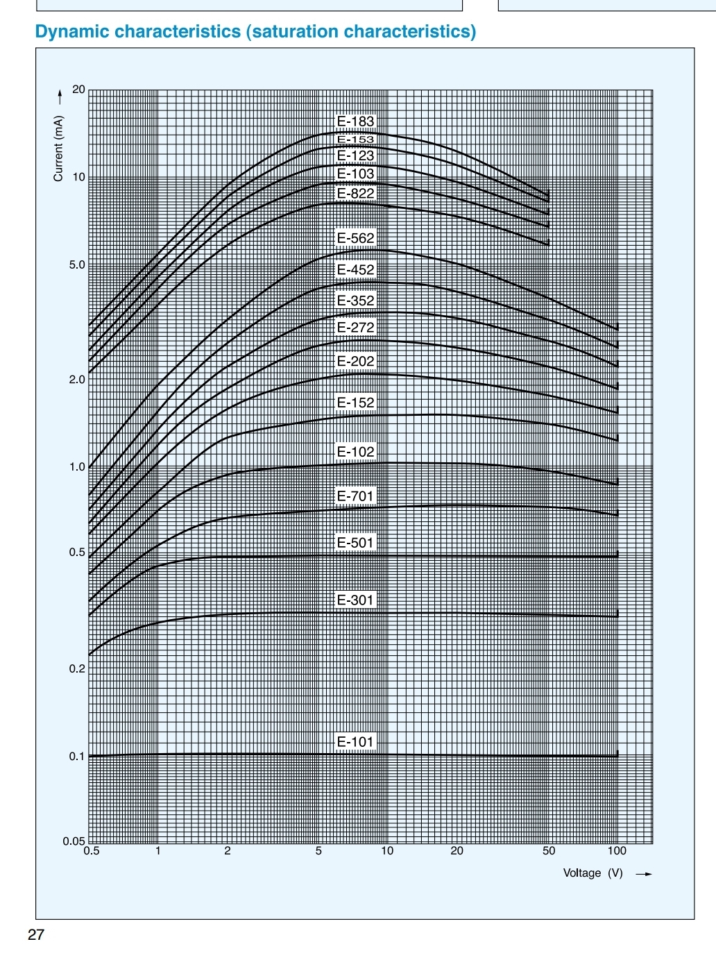
For anyone interested, this is from the data sheet:
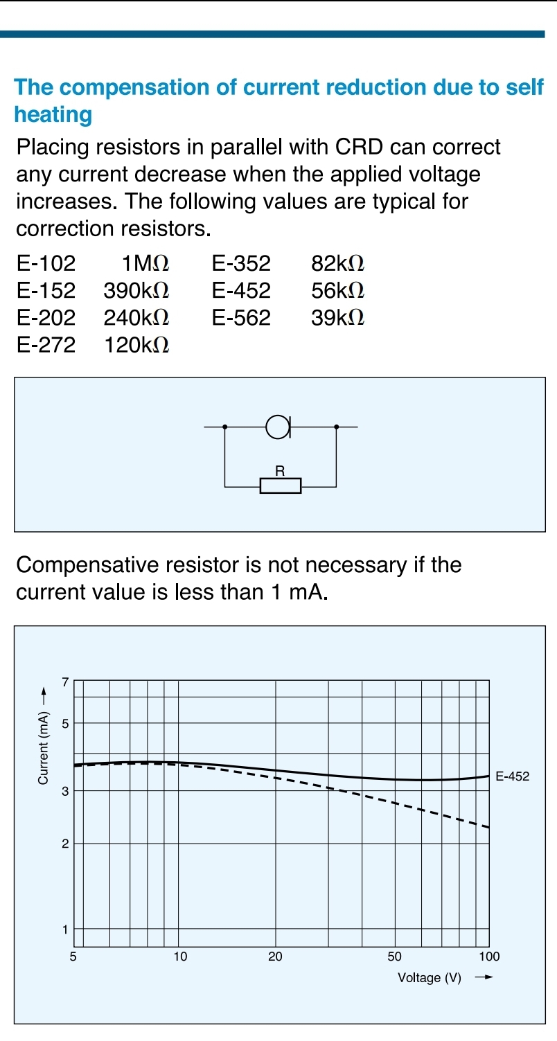
And interestingly it says that the diode can be compensated with a resistor in parallel:
Is the voltage across D75 stable in normal operation?
I'm wondering if there would be any benefit in changing the current source for a more stable one if the current source already has its V/I point fixed by the biasing.
And interestingly it says that the diode can be compensated with a resistor in parallel:
Is the voltage across D75 stable in normal operation?
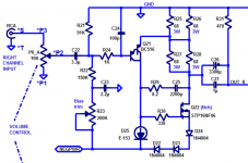
Diodes D72-D74 elevate the source voltage of MOSFET Q72, which in turn elevates its gate voltage. This biases current source D75 to its sweet spot on the I-V curve for best operation, comfortably above the "knee voltage Vk" discussed on the E-153's datasheet.
I'm wondering if there would be any benefit in changing the current source for a more stable one if the current source already has its V/I point fixed by the biasing.
Attachments
Last edited:
I'm wondering if there would be any benefit in changing the current source for a more stable one if the current source already has its V/I point fixed by the biasing.
Much depends on just how fixed the voltage across the E153 is I would guess. There is a sweet spot as Mark points out where the "typical" E153 output impedance will be high but that will be different for each device. Judging by the curve on the data sheet even a small voltage either side of that results in a big change in slope (output impedance). This will dynamically change the open loop gain of the circuit but is that of any great consequence?
I've found a couple of tests on two similar current sources all be it at 1-2mA. The results are probably scaleable. It seems that both the single constant current diode type and the two transistor have a similar output impedance but that the addition of the capacitor to the biasing of the two transistor source gives an additional 30-40dB of line rejection over the constant current diode type. I think this additional line rejection from the RC filtered biasing of the two transistor type is beneficial and is what I hear when I switch to this type of CCS. The LED type that I use offers about 6dB more line rejection compared with the two transistor type, but perhaps it adds more noise??
See here for the two transistor type with capacitor (last two pages) https://www.audioxpress.com/assets/upload/files/AX_Letters_0907.pdf
and here on page seven for the constant current diode type: https://www.audioxpress.com/assets/upload/files/Sources_101_P1.pdf
John
If you don't like any of the 3W Metal Film resistors you see in posts #209 and #211 of this thread, you could use 3W Metal Oxide resistors instead. Wayne Coburn from Pass Labs recommends them.
The ones from KOA Speer cost $0.20 and are in stock. The ones from Panasonic cost $0.56 and are in stock, although they are "NRND" (not recommended for new designs). This is fairly recent; when I bought Panasonic 3W Metal Oxide resistors for my M2x amplifier project two years ago, they were in Active Production.
The ones from KOA Speer cost $0.20 and are in stock. The ones from Panasonic cost $0.56 and are in stock, although they are "NRND" (not recommended for new designs). This is fairly recent; when I bought Panasonic 3W Metal Oxide resistors for my M2x amplifier project two years ago, they were in Active Production.
Ordered my board from Mark on Tuesday and it arrived today. Just 4 days from the US to the UK. Now that's impressive.
Similar here as well
It certainly bugs me that the Akasa Fanless Case I ordered for my Roon Rock Nuc from a company only 60 miles away still hasn't arrived after ten days.
Just a couple of quick questions for @Mark Johnson.
Firstly are the solder points for the heatsinks purely mechanical or are they connected to ground?
Also was there a particular reason this circuit only uses a negative DC current rather than positive or is it just to be different? Just curious.
Regards
Gaz
Firstly are the solder points for the heatsinks purely mechanical or are they connected to ground?
Also was there a particular reason this circuit only uses a negative DC current rather than positive or is it just to be different? Just curious.
Regards
Gaz
Hello Gaz,
I encourage DIYers to exert themselves, to learn, to grow, to steadily advance in the realm of electronics. I encourage you to exert yourself and to apply diligent effort.
You can find the answer to your second question, in the text of post #1 in this thread. I'm sure you've read post #1 at least once, but please read it again, this time looking for the paragraph containing the magic phrase "majority carriers". Voila, that's the paragraph you want today.
You can find the answer to your first question by using your digital multimeter to probe the PCB I shipped to you on September 3rd. Check whether there is, or is not, continuity between the heatsink support pins' plated through holes (labeled "SUPPORT" on the front silkscreen), and any other circuit node (such as ground). Voila, that's the answer you seek.
Hello Gaz,
I encourage DIYers to exert themselves, to learn, to grow, to steadily advance in the realm of electronics. I encourage you to exert yourself and to apply diligent effort.
You can find the answer to your second question, in the text of post #1 in this thread. I'm sure you've read post #1 at least once, but please read it again, this time looking for the paragraph containing the magic phrase "majority carriers". Voila, that's the paragraph you want today.
You can find the answer to your first question by using your digital multimeter to probe the PCB I shipped to you on September 3rd. Check whether there is, or is not, continuity between the heatsink support pins' plated through holes (labeled "SUPPORT" on the front silkscreen), and any other circuit node (such as ground). Voila, that's the answer you seek.
Ahh yes sorry, I read it all again and found what I was looking for. Apologies, cant wait to build it.
For those wishing to calculate the low frequency rolloff when using an X microfarad input capacitor, I recommend assuming that the impedance looking into the base of the PNP Darlington is about 68 Kohms. (i.e. assume its Beta is 2000).
Then I think you'll calculate that the -3dB rolloff occurs at about 1.5 Hz with an input cap of 3.3uF. Reducing the input cap to 1.0uF increases the rolloff frequency to about 5 Hz.
Math: f-3dB = 1 / (2 * pi * Requiv * Cin)
where Requiv is the equivalent resistance driven by Cin. In this case it's (91K || 150K || PNPbase_impedance)
and "||" means "in parallel with"
_
Attachments
Last edited:
As the Darlington is bootstrapped by the output, PNPbase_impedance becomes very high indeed... simulation indicates 30+ megohms. That mainly leaves 91k || 150k = 56.6k, for a -3 dB cutoff @ 2.8 Hz @ 1 µF.
5.6 Hz would be at ca. -0.97 dB (call it -1 dB), 11.2 Hz at ca. -0.26 dB, 22.4 Hz at -0.067 dB and 44.8 Hz at -0.017 dB.
The limit of human perception is about 0.3 dB broadband, and obviously the differences between any two capacitor values >1 µF would be smaller than the values given.
Suffice it to say that I do not believe that any perceived audible difference between 3.3 or 2.2 or 1.5 µF at somewhere around 80-100 Hz would hold up to closer scrutiny (level-matched blind testing or measurements). That's assuming capacitors that aren't competing with a sieve in terms of leakage current for obvious reasons.
Last edited:
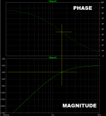
Some folks express concern about the capacitor induced phase shift in the neighborhood of the low frequency rolloff. And indeed with 3.3uF the phase shift has already grown to ten degrees even at 10 Hz. At the -3dB "cutoff" frequency, phase shift is 45 degrees, as thousands of long suffering "Signals And Systems" students can wretchedly attest.
_
_
Attachments
As long as you're enjoying yourself and having a lot of fun with your DIY hobby, then I recommend you do as you please. Experiment with different capacitors. Experiment with different surge protectors / AC mains conditioners. Experiment with different types of volume controls (DACT stepped attenuator / ALPS RK27 pot / etc) as I did in post # 231 on this thread. Experiment with vacuum tubes vs bipolar transistors vs JFETs vs MOSFETs. Experiment with PCBs vs dead bug over groundplane vs point-to-point wiring.
It's all done for entertainment; enjoy the experience. You hear what you hear. Not what somebody else claims you hear. Or what they claim you should / should not hear.
~
It's all done for entertainment; enjoy the experience. You hear what you hear. Not what somebody else claims you hear. Or what they claim you should / should not hear.
~
Last edited:
- Status
- Not open for further replies.
- Home
- Amplifiers
- Headphone Systems
- Single ended class-A headphone amp using two transistors: T2