Hi, I am working on a custom project.
I tried using a LM4808 in a prototype and got function but ultimately its low bass and too high in pitch (slightly headachey). Very thin sound.
I used the exact "Typical application" from the datasheet.
Any ideas on why this is the case? How much can built quality effect the balance? (there is no noticeable buzzing/noise ect)
or any better IC suggestions?
This will be used for 8/16 bit kind of sound so low budget while being balanced/low component is desired.
Thanks.
I took a look at the application circuit. The only power supply decoupling cap is a 100nF electrolytic. Are such caps even made nowadays? Its woefully inadequate for decoupling the power to any audio amplier. I suggest the thin sound can be made fuller by putting a much more substantial capacitor across the rails. Try 3300uF. Also the output coupling caps are too small for reasonable bass at 100uF - increase those to 2200uF.
The second possibility for thin sound is poor layout, if you share the build details I might be able to make suggestions for improvement.
The second possibility for thin sound is poor layout, if you share the build details I might be able to make suggestions for improvement.
Last edited:
And 4.7uf for the input capacitors as well.
The schematic shows an indication of electrolytic caps everywhere, however the part was made for portable devices which use smd ceramic parts almost exclusively. I think it was just an oversight by whomever had drawn the data sheet. Is another reason to only suggest a .1uf cap if there were to be battery power, would probably be fine. Many products like this are competing to make parts that will reduce parts count in mass produced stuff, so they want to advertise that.
I’ve had great luck before with some ic amps by making a great power supply and filtering, is probably not what the company that made them had in mind.
I can look into adding bigger capacitors ect, as phase said its meant to portable so I was expecting to use ceramic smd caps.
Im not tied to this amp IC, or the circuit layout. I dont even remember exactly why I picked this one, maybe its too outdated? No idea.
So any IC that'l hit bass relatively well with ceramics ect if possible. (tantalum at a push) Budget is also in mind so "the best" is not needed.
It will be running 16bit bleepy music.
Maybe premade board like adafruit kits ect I can have a mess with?
Thanks for all the replies =)


I wouldn't worry too much about the sound of X7Rs, they're very unlikely to be the lowest hanging fruit here. Make sure they're adequately sized (in uF terms) and then double or triple the 'sticker' value because of voltage non-linearities. Inadequate amounts of supply decoupling sounds (at least to my ears) considerably worse than X7Rs as coupling caps.
I have a multi meter on route so I'll be able to check the sizes used, and I can reference that against the data sheet if needed.
Correct me if im wrong but from all the chat the decoupling is the key part to get right yeh? Higher value caps is nice and simple =).
(Im a newbie btw)
Ill get back when Iv tested the board =)
Correct me if im wrong but from all the chat the decoupling is the key part to get right yeh? Higher value caps is nice and simple =).
(Im a newbie btw)
Ill get back when Iv tested the board =)
They use something like TPA6132A2 .Im hunting for the best I can without using electrolytics, my goal is a small custom circuit for a portable device. If you can cram sound into a smart phone while still sounding good I must be able too right? how are they pulling it off?
Most smartphones comes with headphone amplifier in their SOC
Another technique is to avoid actual coupling caps and instead control DC and LF with a DC servo circuit. It's more complex, but you can do it in a small footprint. Effectively, the amplifiers allow you to use smaller cap values to obtain longer time constants. Coupling caps, especially those connecting low impedance nodes, must be physically large or have high distortion - some sort of "law pf physics" about dielectric linearity applies, and can't be avoided. If your selection is among commercially available headphone amplifier PCBs, then you are probably out of luck, but technically, it is possible.
Try OPA1688 - in parallel it can drive 150mA. Sounds very nice.
Cheap as Chips OPA1688 Low-THD Muscle Amp
Cheap as Chips OPA1688 Low-THD Muscle Amp
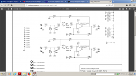
tpa6120 ( ths6012)
TPA6120 Headphone Amplifier - COMPOSITE TOPOLOGY - DIY AUDIO BLOG, AUDIO WORKSHOP
This is what i am using for most of the time and the only am that sound as good as this one is a Kenwood 2x30w amplifier that runs the headphones straight from the speakers output.I run it at 5...10% log volume scale on my headphones.My version of composite tpa 6120 was made by a friend of mine to have smd components and i use opa1642 instead of opa2132 but the sound must be very similar in both versions due to the circuit principle.
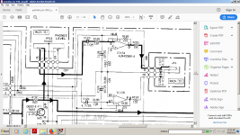
or njm4556 in inverted topology(yamaha kx-930 schematic).
Nothing better in ic form.
TPA6120 Headphone Amplifier - COMPOSITE TOPOLOGY - DIY AUDIO BLOG, AUDIO WORKSHOP
This is what i am using for most of the time and the only am that sound as good as this one is a Kenwood 2x30w amplifier that runs the headphones straight from the speakers output.I run it at 5...10% log volume scale on my headphones.My version of composite tpa 6120 was made by a friend of mine to have smd components and i use opa1642 instead of opa2132 but the sound must be very similar in both versions due to the circuit principle.
or njm4556 in inverted topology(yamaha kx-930 schematic).
Nothing better in ic form.
Attachments
Last edited:
- Status
- This old topic is closed. If you want to reopen this topic, contact a moderator using the "Report Post" button.
- Home
- Amplifiers
- Headphone Systems
- Advice on Headphone amp ICs