I would like some help in selecting a location to connect a power LED on the PCB of a headphone amp that I built. I know a little electronics but I do not understand enough of this headphone amp’s circuits to confidently identify a troublefree location to tap. I have identified two potential locations and I will try to provide enough information so that you might make a recommendation.
The headphone amp is a Sjostrom QRV-08 and is primarily SMDs. I purchased the PCB and BOM from P-A Sjostrom. Schematics were provided but I was asked not disseminate them. The amp is completed, installed in an enclosure and works beautifully. The Chinese enclosure includes a push button power switch with a lighted LED. I have been using the push button but I have never connected the LED. I would like to do that.
I have a red 5mm LED I would like to use and I calculated that connecting to a 25 volt location on the PCB (actually 23.5v) and using a 1500 ohm 2 watt resistor in series will provide adequate illumination and heat dissipation.
Most of the components on the board are tiny but there are two larger components close the edge of the board that would make a suitable location to connect the LED circuit if the connection will cause no harm.
The schematic shows that both of the components are in the +25 volt side of the right channel of the super regulators. There is also an identical -25 volt side for the right channel of the super regulators.
The first potential connecting point is a relatively large V-out on an SOT-223 surface mounted LM317A positive v-regulator close to where the unstable +25 volts enters the super regulator. The relatively large surface area is also designed to dissipate heat. I could connect the LED curcuit to this.
The second potential connecting point is an SOT-223 surface mounted BCP-56-16 NPN transistor. This transistor is similar in appearance to the regulator and has two “collectors”, one of which is relatively large and is designed to dissipate heat. I could connect the LED circuit to this.
Could anyone make an educated guess if either or both of these point would make a suitable connection for the LED circuit. That is power the LED without harming the amplifier.
Any help would be appreciated.
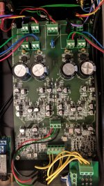
Most of you can probably understand the circuitry by looking at it. You can also see that the attachment points I mentioned are easy to see in the one attachment next to the large capacitors. IC14 is the regulator and the transistor next to G-33 (its not G33) is the NPN transistor.
I now believe that either one of these is an adequate attachment point for the LED circuit. I'm not sure if one is preferred over the other.
I tried the red LED with a 23.56 volt power supply and two 2K 1/2 watt resistors in series and the amount of light emitted seems more than adequate.
I am not 100% sure of the attachment point for the ground but I will probably use the central connection of the 5 place audio signal input connector shown at the bottom of the board. As I have the board wired now there is nothing on this connector. I plan to test and ensure that is indeed grounded.
Attachments

Last edited:
I just found that I had made a mistake on the voltage at the two points I mention above. I just measured at both points and the voltage is 16.53 volts. I haven't determined the value resistor to use but it should be easy to find a small resistor to do the job.
I also confirmed that the ground at the center of the audio signal inputs should work.
I also confirmed that the ground at the center of the audio signal inputs should work.
The easiest, not to mess with the soldering of smd parts, might be to simply wire the led+resistor across the terminals of one of the big caps, under the board.
I will consider this, however, I am quite comfortable soldering SMDs.
I am somewhat concerned with having a wire connected the SMD that might provide enough leverage to cause harm. For this reason I will make this the last connection before I put the top on the enclosure.
I will consider this, however, I am quite comfortable soldering SMDs.
I am somewhat concerned with having a wire connected the SMD that might provide enough leverage to cause harm. For this reason I will make this the last connection before I put the top on the enclosure.
You can use a blob of hot glue to secure the wire to the soldered spot, so that it doesn't wiggle loose while moving the enclosure.
You can use a blob of hot glue to secure the wire to the soldered spot, so that it doesn't wiggle loose while moving the enclosure.
I woke up early this morning thinking about various projects and that's one of the things I thought of. I'm quite sure I will do that.
- Status
- This old topic is closed. If you want to reopen this topic, contact a moderator using the "Report Post" button.
- Home
- Amplifiers
- Headphone Systems
- Headphone Amp: Where to connect Power LED on PCB