
I wonder if anyone has built this amplifier?
I am sure the performance is very good.
Better than most headphone amp suggestions")
I just finished a version. I used a LM4562 op amp. In my case I used FQP3N30/FQP3P20 output devices rather than IRFs. I had no good reason to do that, other than the fact I had some on hand. I also bumped up the circuit gain to 16dB. In use that might prove to be too much and I'll end up dropping it back a bit.
Using FQP3N30/FQP3P20 output devices caused me to add a pair of 10 ohm resistors in series with their source outputs.
I've just started listening to it. So far it sounds to be very good!
Attachments
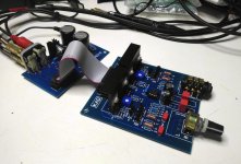
Nice work, Carl Huff! Very neat layout. I bet it sounds great. Few questions: what is the bias current running at and what is the DC offset? Sometimes a bipolar electrolytic (220uF or so) between R11 and ground can keep the offset centered at 0mV.
Thank you for your comments XRK,
The offset is very low, less than a millivolt. I haven't had the opportunity to measure anything beyond that. I checked it briefly with a scope and PC spectrum analyser to verify that it was working and then just plugged it in. I confess, I built it quickly from 'familiar' parts. I am certain that it can be improved upon. In any case it is a very nice circuit that sounds very good! And now I am off traveling on holiday with my wife. I will revisit this project in a couple of weeks and let you know my findings.
That looks great, Carl
Those heatsinks are made by Ohmite and are perfect for these kind of projects.
Mouser stocks them as part #588-CSM221-40AE
> I used FQP3N30/FQP3P20 output devices rather than IRFs. I had no good reason to do that …
I have. The FQP’s are truer complementary devices than the IRF’s.
Check out the F5 Headamp thread at the Pass forum.
F5 Headamp ?
Posts #195, 196, 205
> Using FQP3N30/FQP3P20 output devices caused me to add a pair of 10 ohm resistors in series with their source outputs.
For fear of thermal run-away ?
They won’t when you have enough heatsink.
I have used 3.3R with no issues.
> The offset is very low, less than a millivolt.
Comes with the opamp. Any output stage offset will be corrected by the NFB loop of the opamp.
> I am certain that it can be improved upon.
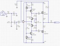
Replacing R1 with a current source (e.g. E252) will improve PSRR.
And you can simplify the circuit a lot by replacing the Vbe multipliers with 2 resistors.
See :
DIYForums.org • View topic - discrete diamond buffers
https://www.amb.org/ti/audio/mosfet_buffer_sch.png
> Those heatsinks are made by Ohmite and are perfect for these kind of projects.
> Mouser stocks them as part #588-CSM221-40AE
Thermal resistance is 12°C/W.
Assuming +/-15V supplies and 100mA bias per channel (per heatsink), temperature rise is 36°C above ambient. So HOT !
And the vertical MOSFETs (whether FQP or IRF) have positive tempco.
Which means bias will increase with temperature which in turn will increase bias further.
That is why a large heatsink is advantageous, so as lateral MOSFETs because of negative tempco.
The XEN XELF Headphone Buffer
Cheers,
Patrick
I have. The FQP’s are truer complementary devices than the IRF’s.
Check out the F5 Headamp thread at the Pass forum.
F5 Headamp ?
Posts #195, 196, 205
> Using FQP3N30/FQP3P20 output devices caused me to add a pair of 10 ohm resistors in series with their source outputs.
For fear of thermal run-away ?
They won’t when you have enough heatsink.
I have used 3.3R with no issues.
> The offset is very low, less than a millivolt.
Comes with the opamp. Any output stage offset will be corrected by the NFB loop of the opamp.
> I am certain that it can be improved upon.
Replacing R1 with a current source (e.g. E252) will improve PSRR.
And you can simplify the circuit a lot by replacing the Vbe multipliers with 2 resistors.
See :
DIYForums.org • View topic - discrete diamond buffers
https://www.amb.org/ti/audio/mosfet_buffer_sch.png
> Those heatsinks are made by Ohmite and are perfect for these kind of projects.
> Mouser stocks them as part #588-CSM221-40AE
Thermal resistance is 12°C/W.
Assuming +/-15V supplies and 100mA bias per channel (per heatsink), temperature rise is 36°C above ambient. So HOT !
And the vertical MOSFETs (whether FQP or IRF) have positive tempco.
Which means bias will increase with temperature which in turn will increase bias further.
That is why a large heatsink is advantageous, so as lateral MOSFETs because of negative tempco.
The XEN XELF Headphone Buffer
Cheers,
Patrick
One can find many many variants of headphone amplifiers being made up of an opamp driving a emitter or source follower.
Apart from opamp rolling, the major difference is in the output devices being used, the biasing method, and the thermal stabilisation.
One can of course use TO220 (or larger) BJTs or MOSFETs.
But one could also use a number (say 10x) of TO92 BJTs or JFETs in parallel.
These will require matching and degeneration to ensure equal current sharing.
If the output devices have positive tempco, they will run away thermally, which can be mitigated with :
sufficient heat sinking
emitter / source degeneration
some form of thermal compensation (such as NTC's)
some form of auto-biasing circuit (such as in the WHAMMY or JLH headphone amp)
Auto-Biasing Circuits for Complementary Followers
Or better still, you use a device with negative tempco at bias, so that it is self stabilising.
The other major difference in the biasing circuits is how much of a AC or DC load they present to the opamp.
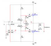
A current source based design in post #1 is e.g. a much easier load for the opamp than the 2-resistor solution in post #32.
There are ever simpler biasing circuits but these are not self contained and relies on the opamp to correct for everything.
An example can be found in Fig 4 :
https://www.diyaudio.com/forums/att...-buffer-xelf-lateral-mosfet-buffer-public-pdf
They will all have their own different sonic signatures, be it minute.
But they will all have the characteristic sound of a high NFB circuit.
(And nothing wrong with that. All personal taste.)
Cheers,
Patrick
Apart from opamp rolling, the major difference is in the output devices being used, the biasing method, and the thermal stabilisation.
One can of course use TO220 (or larger) BJTs or MOSFETs.
But one could also use a number (say 10x) of TO92 BJTs or JFETs in parallel.
These will require matching and degeneration to ensure equal current sharing.
If the output devices have positive tempco, they will run away thermally, which can be mitigated with :
sufficient heat sinking
emitter / source degeneration
some form of thermal compensation (such as NTC's)
some form of auto-biasing circuit (such as in the WHAMMY or JLH headphone amp)
Auto-Biasing Circuits for Complementary Followers
Or better still, you use a device with negative tempco at bias, so that it is self stabilising.
The other major difference in the biasing circuits is how much of a AC or DC load they present to the opamp.
A current source based design in post #1 is e.g. a much easier load for the opamp than the 2-resistor solution in post #32.
There are ever simpler biasing circuits but these are not self contained and relies on the opamp to correct for everything.
An example can be found in Fig 4 :
https://www.diyaudio.com/forums/att...-buffer-xelf-lateral-mosfet-buffer-public-pdf
They will all have their own different sonic signatures, be it minute.
But they will all have the characteristic sound of a high NFB circuit.
(And nothing wrong with that. All personal taste.)
Cheers,
Patrick
- Status
- This old topic is closed. If you want to reopen this topic, contact a moderator using the "Report Post" button.
- Home
- Amplifiers
- Headphone Systems
- Class A Headphone Amp; OPA827 and IRF610/9610