I've been wrestling with compensation issues with the Darlington - based incarnation of this amp, probably mostly due to the much higher transconductance of the Darlington devices compared to the mosfets previously used. I'm encountering a nasty resonance at around 2MHz which causes the amp to be conditionally stable, even though the time domain transient response looks relatively benign. I think the path to success will be to tone down the bias current on all stages except for the output - we'll see. I've also experimented with several placements for compensation, though none appears to be the silver bullet needed.
As a tide - me- over, I did a sim using Patrick's modulated current source scheme. As an aside, it looks like I used a similar circuit in one of my explorations for a "J2MeToo" sort of amplifier. See post #47 of this thread - IXYS 200V Depletion Mode Mosfet Now Available
Anyway, here's the implementation using a mosfet/bipolar current source, and the sim distortion results - respectable. The driven current source is also providing properly mirrored output drive. I ginned up a board using a simpler approach to this concept over the weekend, and I'll be putting the circuit through its paces when I get the time.
Attachments
Last edited:
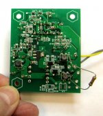
Here's the latest version of the Aleph HP amp using a depletion mode mosfet for the topside modulated current source. I'll be spinning this amp in two versions, one biased for headphone use, and one with a larger depletion mode fet for use as a ~5W class A amp to power some computer speakers I'm designing using huge PVC pipe elbows for the enclosures.
Attachments
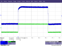
Here's the simulated time domain response to a 10 kHz square wave with 50 ns edges. The plots are expanded to show detail of the rise and fall times. I''ll be seeing soon whether the amp is actually as fast as the sim indicates. If I remember correctly, my signal generator square wave has only 100 ns edges, so the output may look very much like the input. I'm hoping for no funky ringing or overshoot.
Attachments
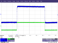
I finally managed to sit down and feed the amplifier with a square wave to get the response - things look agreeable... I will proceed with boxing up a couple of boards for listening rests, as well as spinning a version with 5-10W/channel, depending on how much dissipation I can handle with the TO-220 devices currently in place.
Attachments
Here's improved transient response resulting from tweaking the rail voltages a bit. I'm going to have to poke around and study the schematic until I understand the sensitivity to rail voltage, though I have a notion... At any rate, I'm happy to see the improved response - zippy little critter. I'm reluctant to reveal the schematic, as I have had promising IP re headphone amp designs stolen & bowdlerized without original design credit in this forum before.
Attachments
Last edited:

Here's improved transient response resulting from tweaking the rail voltages a bit. I'm going to have to poke around and study the schematic until I understand the sensitivity to rail voltage, though I have a notion... At any rate, I'm happy to see the improved response - zippy little critter. I'm reluctant to reveal the schematic, as I have had promising IP re headphone amp designs stolen & bowdlerized without original design credit in this forum before.
Yes I can think of one person who did that to you! Disgusting how he was allowed to get away with it too! I even got infracted for calling said person out for belittling and patronising behaviour!
I've been working my way through various issues re the sensitivity of the square wave response to rail voltage, and I think I now understand what is going on. I'll be doing some tweaking, and will post more pics when I have them.
What I've found will also be relevant to scaling up this amp for speaker duty.
What I've found will also be relevant to scaling up this amp for speaker duty.
Last edited:
Yeah, smug and condescending is his middle name...
2nd that
middle and last name C-J author extraordinaire
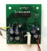
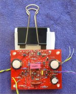
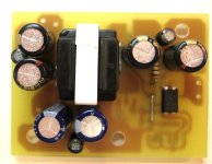
Here's an alternate flyback supply based on a classic "ringing choke" topology, used for generating the two negative supplies used on this amp from a 12V switching wall-wart that will power the positive supply. There is no IC controller, just a couple of bipolar transistors and a p-channel mosfet. As an experiment, I'm using a powdered iron E core instead of ferrite as the core of the transformer. I may switch back to ferrite if the losses are excessive, but if it works, the powdered iron removes the necessity of grinding a gap for the core, which is needed for ferrite.
Attachments
Last edited:
This morning I got the ringing choke converter up and running. Operating frequency is markedly lower that expected - I suspect it's due to the increase in permeability in a powdered iron core with AC excitation. I'm using Micrometals mix 52, which can double in permeability as a function of AC excitation. The low level inductance measurement shows a value close to the target of 200 uH. The current waveform shows an inductance value of almost twice the low level value. I'm going to try cutting the turns on the inductor and see what happens...
Micrometals mix 52 data
-52 - Mix 52 - Micrometals
Micrometals mix 52 data
-52 - Mix 52 - Micrometals
Last edited:
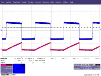
Here's the drain voltage and current for the ringing choke converter, so you can see my concern. The blue is the drain voltage (10 V/div), and the red is the drain current (1A/div). On the negative half of the drain voltage wavefrom, the trailing edge shows a characteristic rounding that shows that the converter is operating in borderline discontinuous mode, as it should. The slope of the drain current shows a large signal inductance of almost twice that of the small signal inductance value of 200uH. I will also be subbing a switch FET with lower RDSon, to counter the voltage droop happening during the device on-time.
Attachments
- Status
- This old topic is closed. If you want to reopen this topic, contact a moderator using the "Report Post" button.
- Home
- Amplifiers
- Headphone Systems
- Aleph-Based Headphone Amp