Hi,
I am taking the reference of LME49600 evaluation board design and modify it for my own. I change the opamp to be OPA627 and buffer to be BUF634. I use LME49720 for DC servo for both channels. I also change the feedback resistors so that the gain is 11.
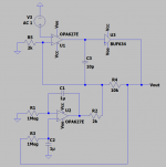
I want to make the amp more stable and I am going to add a 10pF compensation cap for this design. The question is, should I place the compensation cap C3 in parallel with feedback resistor R4 (Diagram 1)? Or should I place it across the OPA627 output PIN and negative input PIN(Diagram 2)?
I am taking the reference of LME49600 evaluation board design and modify it for my own. I change the opamp to be OPA627 and buffer to be BUF634. I use LME49720 for DC servo for both channels. I also change the feedback resistors so that the gain is 11.
I want to make the amp more stable and I am going to add a 10pF compensation cap for this design. The question is, should I place the compensation cap C3 in parallel with feedback resistor R4 (Diagram 1)? Or should I place it across the OPA627 output PIN and negative input PIN(Diagram 2)?
Attachments
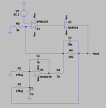
should I place the compensation cap C3 in parallel with feedback resistor R4?
Or should I place it across the OPA627 output PIN and negative input.
Connect the C3 directly to the OPA627 output.
Last edited:
Your design doesn’t need that cap.
OPA627 is a unity gain stable, your design have a gain of -5.
Also compare offsets of 627 and 49720, Higher grade of 627 is an order more precise in terms of input offset voltage and a three-to-five orders precise in terms of input bias and offset current.
Go further.
Simple op amp + BUF634 HPA
OPA627 is a unity gain stable, your design have a gain of -5.
Also compare offsets of 627 and 49720, Higher grade of 627 is an order more precise in terms of input offset voltage and a three-to-five orders precise in terms of input bias and offset current.
Go further.
Simple op amp + BUF634 HPA
As mentioned, Diagram 2, assuming you need on at all (can't hurt to have a spot reserved for it).
R4/5 can easily be reduced by a factor of 2.
R2, by contrast, is too small - the servo only needs to provide a tiny amount of adjustment (xx mV), and may introduce excessive low-frequency noise like this. In all likelihood, 100 x R5 (so e.g. 100 kOhm) would be perfectly sufficient. Then it doesn't have to be a fancy opamp either - a TL07x will do in a pinch, though a precision model with slightly better input offset spec may be desirable.
So in sum - R4 = 4k7, R5 = 470R, R2 = 47k.
A gain of 11 seems a bit high unless you have rather low source levels... such an amp will only output 6-9 Vrms after all, depending on supplies. From experience, a CD player will often require no more than unity gain for 102 dB/V headphones (e.g. Sennheiser HD6xx, Beyer DT880 and similar).
Last edited:
As mentioned, Diagram 2, assuming you need on at all (can't hurt to have a spot reserved for it).
R4/5 can easily be reduced by a factor of 2.
R2, by contrast, is too small - the servo only needs to provide a tiny amount of adjustment (xx mV), and may introduce excessive low-frequency noise like this. In all likelihood, 100 x R5 (so e.g. 100 kOhm) would be perfectly sufficient. Then it doesn't have to be a fancy opamp either - a TL07x will do in a pinch, though a precision model with slightly better input offset spec may be desirable.
So in sum - R4 = 4k7, R5 = 470R, R2 = 47k.
A gain of 11 seems a bit high unless you have rather low source levels... such an amp will only output 6-9 Vrms after all, depending on supplies. From experience, a CD player will often require no more than unity gain for 102 dB/V headphones (e.g. Sennheiser HD6xx, Beyer DT880 and similar).
Hi,
Thanks for your comment. But I still can't understand why R2 need to set to high?
One more question, if I need to match the input impedance of two differential input of OPA627, I need to add a 430R resistor in OPA627 (+) terminal, right? Should I place the resistor in series or in parallel??
BTW The gain here is 6, not 11....
Agree that comp cap is not needed.
Jan
No, it is 11. The gain is calculated by (R4/R5//R2) + 1 which is 11
No, it is 11. The gain is calculated by (R4/R5//R2) + 1 which is 11
Ahh yes, you are correct!
BTW I think it has been stated already that that R2 is very low, too low actually, bringing the opportunity of any residual lf, noise and output impedance variations from the servo to creep back into the signal. The servo only has to provide very small correction signals anyway, and a more usual, more clean value for R2 would be like 200k or more which further decreases junk from the servo by another 40dB or so while keeping the servo action intact.
That would also take R2 out of the gain equation.
Jan
- Home
- Amplifiers
- Headphone Systems
- Where should the compensation cap be placed?