Hi everyone
Just ordered the necessary parts for a "The Wire" clone. I already have everything for a PSU together:

As you can see, the transformer has twice the amount of windings that would strictly be necessary to provide symmetric power to the ICs.
This enables me to also give this project a symmetric power output for a phono stage or something of the likes
I'm hoping this PSU will be sufficient for powering my choice of ICs:
The LME49600 as a buffer.
For gain, the OPA209 http://www.ti.com/lit/ds/symlink/opa209.pdf with a small slew rate and overall good specs
or ADA4807
with a much bigger slew rate but extremely low THD+N
(source: cyfi.com).
However, specs are not everything, hopefully this will help me to relate them to RL.
This is how I plan to wire it all up:
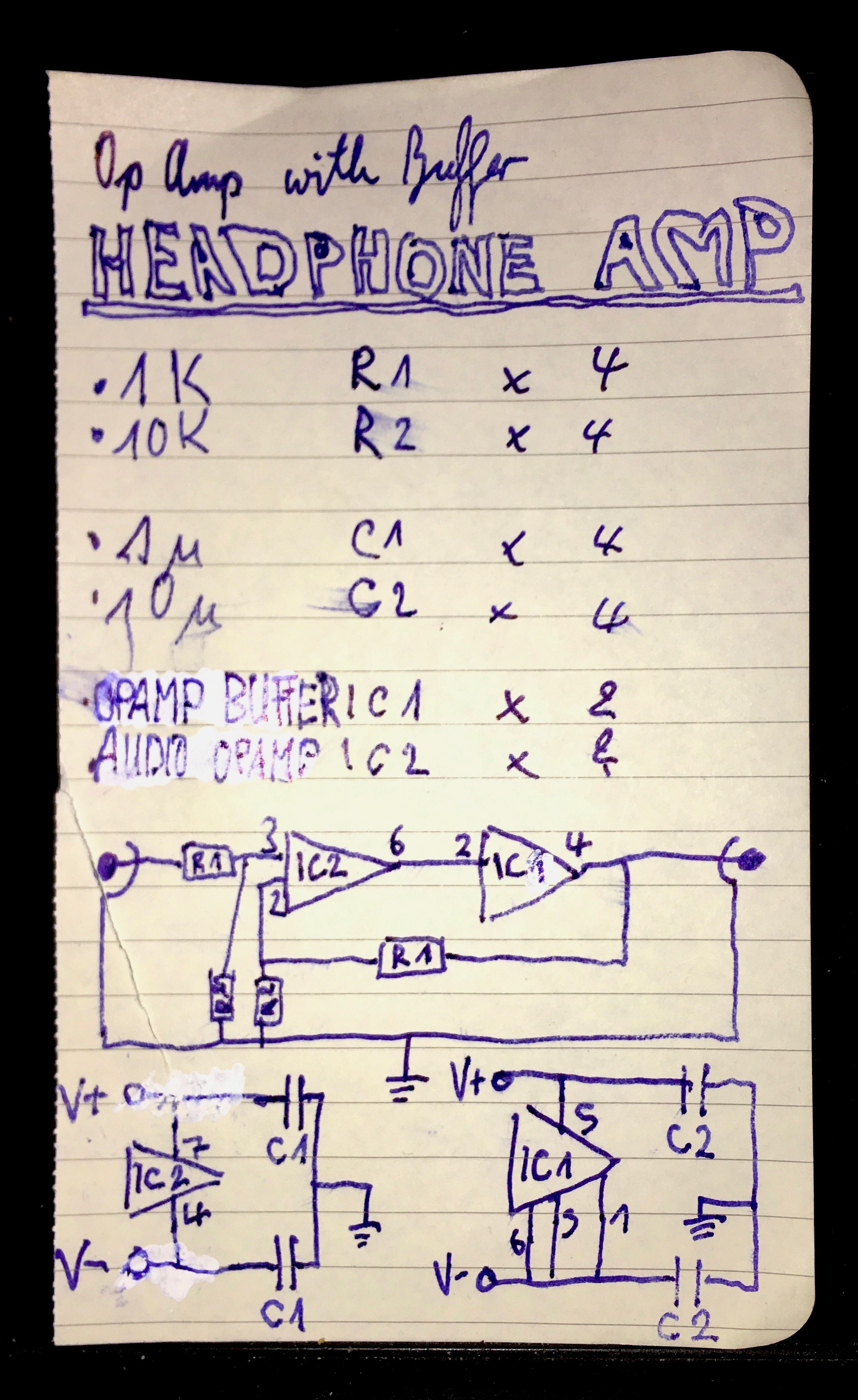
This is a very simple construction, but I am using the best (to a sensible degree) components that I can find.
Not entirely sure if this is a valid approach, as the circuit design should play a bigger role than component quality.
This way I am hoping to get a pretty accurate and reliable device for my first HA.
Thats it for now, if you have any thoughts or tips, thats much appreciated
Just ordered the necessary parts for a "The Wire" clone. I already have everything for a PSU together:
As you can see, the transformer has twice the amount of windings that would strictly be necessary to provide symmetric power to the ICs.
This enables me to also give this project a symmetric power output for a phono stage or something of the likes
I'm hoping this PSU will be sufficient for powering my choice of ICs:
The LME49600 as a buffer.
For gain, the OPA209 http://www.ti.com/lit/ds/symlink/opa209.pdf with a small slew rate and overall good specs
or ADA4807
with a much bigger slew rate but extremely low THD+N
(source: cyfi.com).
However, specs are not everything, hopefully this will help me to relate them to RL.
This is how I plan to wire it all up:
This is a very simple construction, but I am using the best (to a sensible degree) components that I can find.
Not entirely sure if this is a valid approach, as the circuit design should play a bigger role than component quality.
This way I am hoping to get a pretty accurate and reliable device for my first HA.
Thats it for now, if you have any thoughts or tips, thats much appreciated
Last edited:
What do you plan on for supply voltages? Asking because those 6 V secondaries are a bit on the low side. Should be good for a regulated +/-5 V or so, or a bit more with LDOs. If you want something higher you'd have to use all of them after all (with two in series each). Not a real biggie, plenty of amps share a phono stage supply with other things (though possibly with additional cleanup).
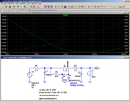
With all those big 10000µ caps, you may end up not needing any regulators at all.
[thumb]https://www.diyaudio.com/forums/attachment.php?attachmentid=728290&stc=1&d=1547243514[/thumb]
Over 70 dB of ripple rejection at 100 Hz for a voltage drop of ~600 mV in idle is not too shabby, I say... circuit PSRR should take care of the rest. Of course, if your circuit draws 200 mA under load, that'll be a 4 V drop. A capacitance multiplier may be the better choice.
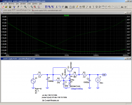
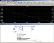
Attached you'll find two versions with cap multipliers, both similar in performance (128-129 dB RR @100 Hz - it goes without saying that proper ground routing is imperative), though the Darlington makes up for its complexity by keeping up the output voltage more constant under load. Interestingly enough, putting the MOSFET cap multiplier in the middle resulted in better CMRR than with it at the end, I guess it may have highish output impedance and that adds to R2, improving RC filtering.
The negative rail would be equivalent, just flipped and with p-channel / pnp devices.
As for the circuit itself, I guess about 100 pF at the input for RF rejection might not be bad, and I would include a spot for a small capacitor from IC2 output to -in for loop compensation.
Having separate power and signal ground returns is advised. As the main filters are so big, I would include some additional electrolytics for the supplies, like 220 µF, with something low ESR with ~10 µF for bypass.
R1/2 are higher than optimum for a low input noise part, and a gain of 11 may prove excessive depending on source level and headphones used.
You must have gotten the part number for that AD part wrong, I can't find it. Speaking of opamps, you could try something like an NE5534(A) first. (Fit compensation cap as required.)
(If the project drags on, you could always order a JDS Labs Atom or something to tide you over, with a volume control and variable gain already included, but where's the fun in that?)
With all those big 10000µ caps, you may end up not needing any regulators at all.
[thumb]https://www.diyaudio.com/forums/attachment.php?attachmentid=728290&stc=1&d=1547243514[/thumb]
Over 70 dB of ripple rejection at 100 Hz for a voltage drop of ~600 mV in idle is not too shabby, I say... circuit PSRR should take care of the rest. Of course, if your circuit draws 200 mA under load, that'll be a 4 V drop. A capacitance multiplier may be the better choice.
Attached you'll find two versions with cap multipliers, both similar in performance (128-129 dB RR @100 Hz - it goes without saying that proper ground routing is imperative), though the Darlington makes up for its complexity by keeping up the output voltage more constant under load. Interestingly enough, putting the MOSFET cap multiplier in the middle resulted in better CMRR than with it at the end, I guess it may have highish output impedance and that adds to R2, improving RC filtering.
The negative rail would be equivalent, just flipped and with p-channel / pnp devices.
As for the circuit itself, I guess about 100 pF at the input for RF rejection might not be bad, and I would include a spot for a small capacitor from IC2 output to -in for loop compensation.
Having separate power and signal ground returns is advised. As the main filters are so big, I would include some additional electrolytics for the supplies, like 220 µF, with something low ESR with ~10 µF for bypass.
R1/2 are higher than optimum for a low input noise part, and a gain of 11 may prove excessive depending on source level and headphones used.
You must have gotten the part number for that AD part wrong, I can't find it. Speaking of opamps, you could try something like an NE5534(A) first. (Fit compensation cap as required.)
(If the project drags on, you could always order a JDS Labs Atom or something to tide you over, with a volume control and variable gain already included, but where's the fun in that?)
Attachments
Last edited:
Ok, after some reading it looks like this not really gonna be a wire clone after all.
The HA will be supplied by a single OPA134 per channel in a VSPS phono stage.
This is also what the aux power was meant for, it will be put in parallel with the gain circuits.
Thanks a lot for the good suggestions for the power supply, Ive decided that this will be a future improvement. I also own a SymAsym 5.3 based speaker amp that could benefit off that kind of ripple rejection
Also what do you mean with in-loop compensation between the ICs? how would I find the right value?
Here is the current state of the circuit:

First off, one chassis ground for the PSU and one for left, right gain circuit
Left and right will be separately decoupled with 10u and 0u1 caps.
Gain is set by 2k2 input resistor and 4k7 or 10k, to see what is appropriate for my 80r DT770.
Also decided to go with inverting because I want the lowest possible distortion.
Adding the Bandwidth pin on the buffer in is a good thing I guess?
Not entirely sure about my choice of output resistor and output coupling here, just tried to go with standard values.
A RF protection cap will not be omitted, I forgot adding it on this drawing.
Also got myself a nice 10k pot, this goes between all the circuitry and the headphone.
The HA will be supplied by a single OPA134 per channel in a VSPS phono stage.
This is also what the aux power was meant for, it will be put in parallel with the gain circuits.
Thanks a lot for the good suggestions for the power supply, Ive decided that this will be a future improvement. I also own a SymAsym 5.3 based speaker amp that could benefit off that kind of ripple rejection
Also what do you mean with in-loop compensation between the ICs? how would I find the right value?
Here is the current state of the circuit:
First off, one chassis ground for the PSU and one for left, right gain circuit
Left and right will be separately decoupled with 10u and 0u1 caps.
Gain is set by 2k2 input resistor and 4k7 or 10k, to see what is appropriate for my 80r DT770.
Also decided to go with inverting because I want the lowest possible distortion.
Adding the Bandwidth pin on the buffer in is a good thing I guess?
Not entirely sure about my choice of output resistor and output coupling here, just tried to go with standard values.
A RF protection cap will not be omitted, I forgot adding it on this drawing.
Also got myself a nice 10k pot, this goes between all the circuitry and the headphone.
I hope that's not literally what it looks like. Spot the difference.Here is the current state of the circuit:
(Hint: Transformers tend not to appreciate DC too much.
)Do you have any plans for a chassis ground to PE connection? Make sure you are aware of the implications of using unbalanced inputs in an IEC Class I device if so, and the electrical safety requirements for a Class II device otherwise.First off, one chassis ground for the PSU and one for left, right gain circuit
Have you considered the implications on input impedance?Gain is set by 2k2 input resistor and 4k7 or 10k, to see what is appropriate for my 80r DT770.
Also decided to go with inverting because I want the lowest possible distortion.
Shouldn't hurt.Adding the Bandwidth pin on the buffer in is a good thing I guess?
Way off on both counts.Not entirely sure about my choice of output resistor and output coupling here, just tried to go with standard values.
You know what the low end -3 dB point is with a 16 ohm load? 624 Hz. Or 548 Hz with 32 ohms. Or 121 Hz with 600 ohms.
Looks like you should be reading up on how to calculate cutoff frequency from time constant. It's
f_c = 1 / (2 π τ)
with
τ = (R_out + Z_load,nom) * C_out
You will probably find the required values for low-impedance cans to be a tad on the cumbersome side. Actually you don't even need a cap on the output side since you have a split supply - if anything, I'd include one on the input side, if just to keep opamp input bias current away from the pot (mostly a concern for bipolar input parts without input current cancellation, not a concern for FET input parts where I'd put it ahead of the pot). Sizing is generally for f_c ~= 2 Hz or thereabouts.
100-120 ohm has not been considered "standard" output impedance in a long time. These days you are generally better off with 10 ohms maximum. That should do fine for a DT770-80, with something like a HD598 I'd aim for <5 ohms, and some multi-driver BA jobs require <1 ohm.
Maximum source impedance for a standard volume pot setup is Rpot/4, i.e. 2.5 kOhms. Check how this relates to circuit input impedance.Also got myself a nice 10k pot, this goes between all the circuitry and the headphone.
Last edited:
Hi again 
So... I realised that building this amp is gonna require some more learning on my part. Though quiet on the forum, I've been busy in real life.
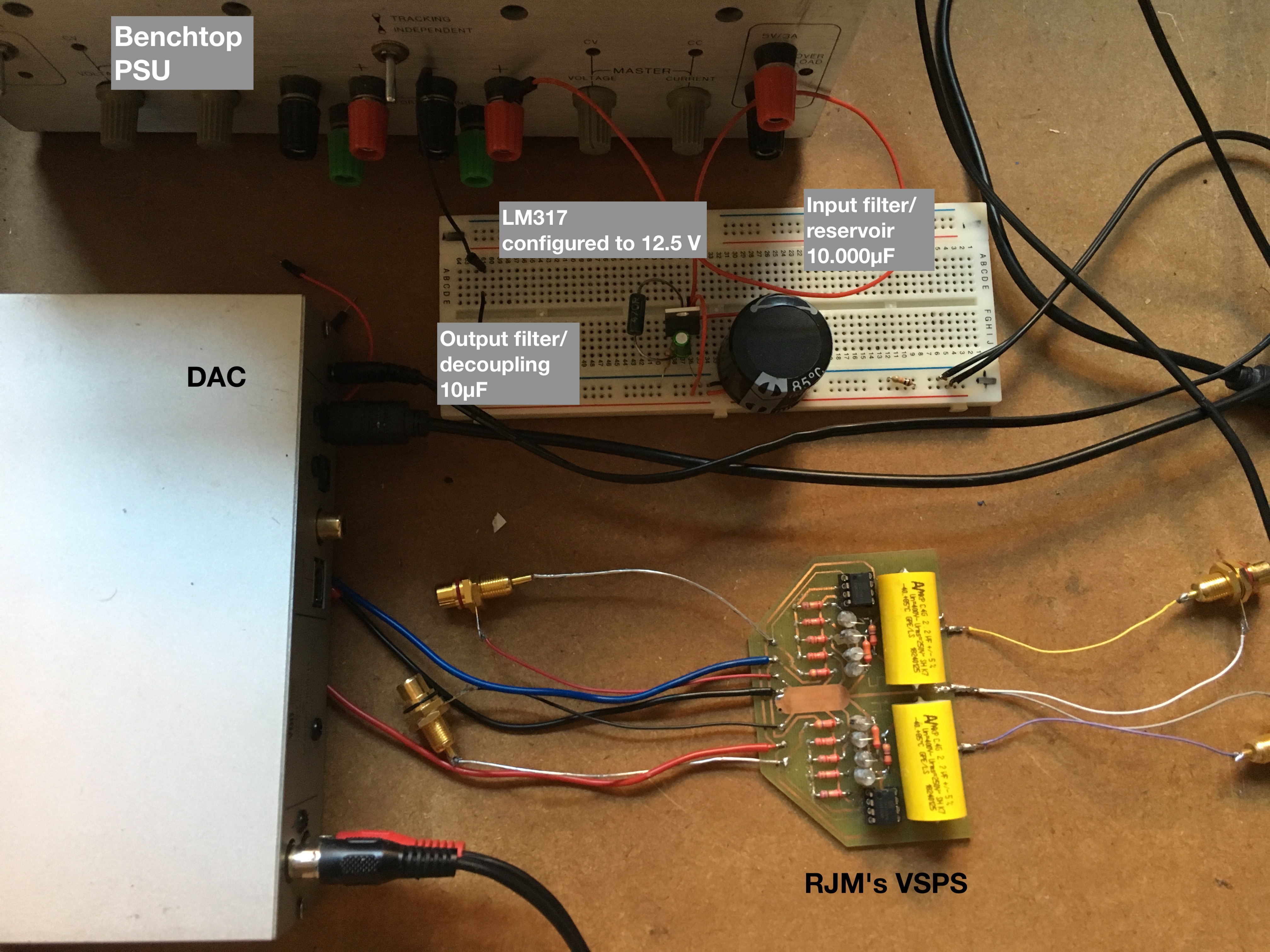
This is a Phono Stage (circuit by RJM), that works great without obvious issues. Also a regulated PSU powering a V90-DAC, inspired by the kind suggestions of @sgrossklass. At the moment the PSU is powered by a noisy bench supply but it is a real improvement over the stock wall adapter. So far so good.
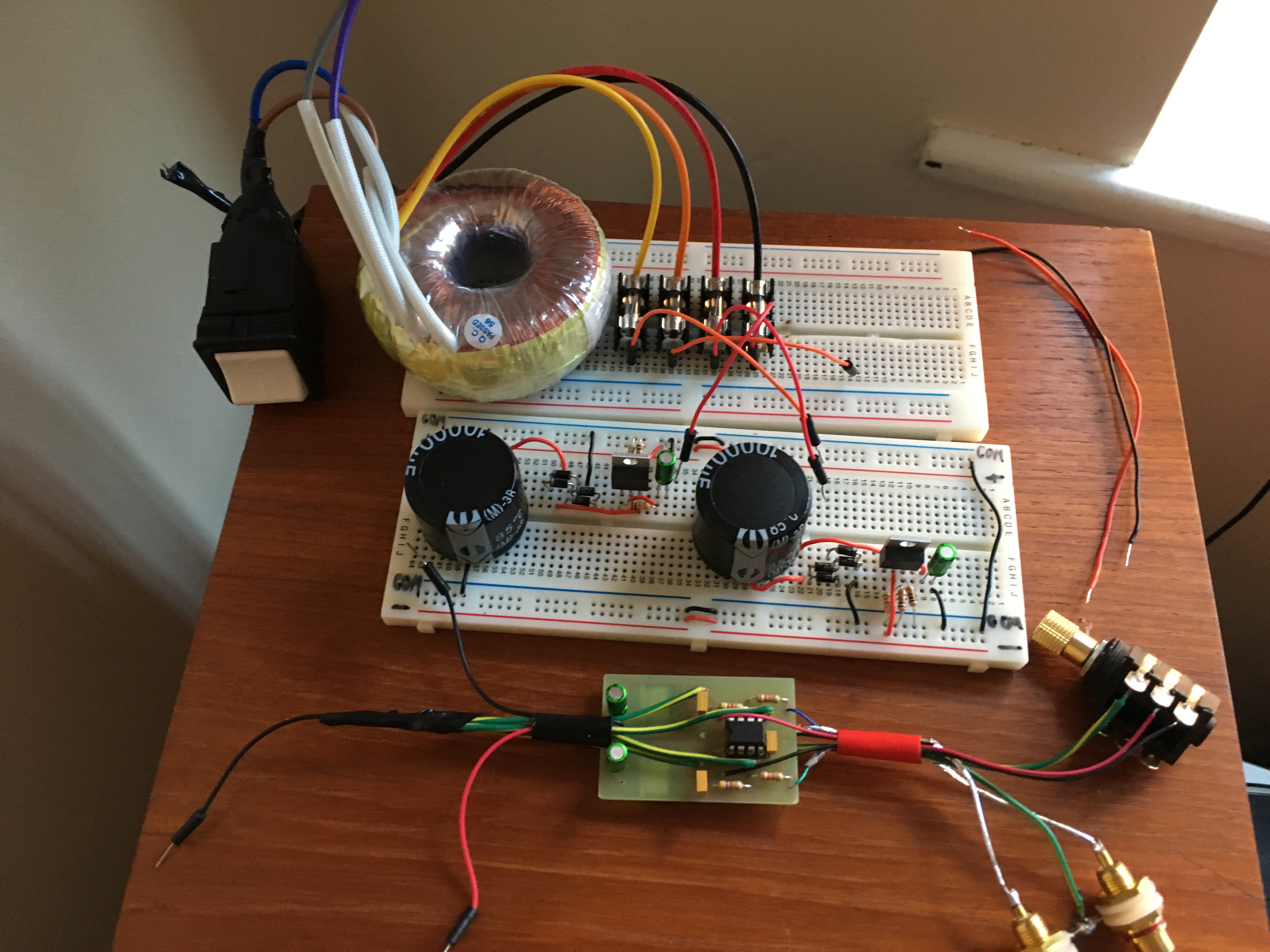
These two circuits are not yet working. The puzzling (to me ) issue is that the dual PSU only works off a bench supply. Full wave rectified +/-15V input overheats the LM317/ LM337 regulators and adjustment resistors very quickly at 12V DC output. Not too bothered with the amp atm, want to suss out the power first.
While making progress, I'm probably making some basic mistakes here which prevent the regulators from working.
So... I realised that building this amp is gonna require some more learning on my part. Though quiet on the forum, I've been busy in real life.
This is a Phono Stage (circuit by RJM), that works great without obvious issues. Also a regulated PSU powering a V90-DAC, inspired by the kind suggestions of @sgrossklass. At the moment the PSU is powered by a noisy bench supply but it is a real improvement over the stock wall adapter. So far so good.
These two circuits are not yet working. The puzzling (to me
) issue is that the dual PSU only works off a bench supply. Full wave rectified +/-15V input overheats the LM317/ LM337 regulators and adjustment resistors very quickly at 12V DC output. Not too bothered with the amp atm, want to suss out the power first. While making progress, I'm probably making some basic mistakes here which prevent the regulators from working.
Honestly, I can't make heads or tails of your rectifiers. It looks like they are missing multiple connections, the left one (positive I think) seems to be floating in thin air altogether.
You also don't have 4 secondaries as you intended but rather just two. The middle two wires should be combined and go to COM.
You also don't have 4 secondaries as you intended but rather just two. The middle two wires should be combined and go to COM.
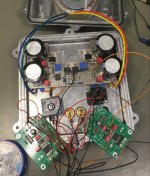
Hello again, it has been over a year now of struggle and confusion, sleepless nights and a LOT of learning. Happy to report at this point that the amp is working! And cased up in a wayy to tight chassis. A shoutout to user sgrossklass for his kind advice when the project was still looking like a hopeless case.
On the technical side, I bought a VentusEZ boardkit for the amp, as this is exactly what I was trying to build before I had any idea of what I was doing. For the power supply section a linear regulated "El Generico" design with oversized filter caps. Strict star-grounding is maintained, keeping high-current grounds away from low current ones where they meet. The amp is absolutely dead silent.
But working does not mean finished
 I would like to rebuild the insides with a few more bells and whistles, like a power switch. On a more serious note, the power supply I intended to build, I cannot get it to work fully. The two opa548 overheat at low currents, maybe ESD damage. If anyone has experience with these guys, do feel free to share your two cents.
Also welcoming any possible ideas on other power supply improvements.
On the technical side, I bought a VentusEZ boardkit for the amp, as this is exactly what I was trying to build before I had any idea of what I was doing. For the power supply section a linear regulated "El Generico" design with oversized filter caps. Strict star-grounding is maintained, keeping high-current grounds away from low current ones where they meet. The amp is absolutely dead silent.
But working does not mean finished
I would like to rebuild the insides with a few more bells and whistles, like a power switch. On a more serious note, the power supply I intended to build, I cannot get it to work fully. The two opa548 overheat at low currents, maybe ESD damage. If anyone has experience with these guys, do feel free to share your two cents. Also welcoming any possible ideas on other power supply improvements.
Attachments
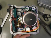
The OPA548 may oscillate. Datasheet shows necessary power supply decoupling capacitors from both rails to ground and between the rails directly at the op-amp power pins. I see none in your design.
What is the reason for such a PSU design with oversized transformer? There are definitely easier ways to make a decent PSU.
Regards,
Oleg
What is the reason for such a PSU design with oversized transformer? There are definitely easier ways to make a decent PSU.
Regards,
Oleg
The transformer in close proximity to your amp inputs will have EMI that can’t be suppressed really - just too close and too big of a trafo in that box.
50/100/200Hz mains hum will be prevalent and might be tough to get rid of.
For a project like this, something like an external linear Class 2 wall wart with 12v or 24v powering an isolated DC-DC SMPS like a Meanwell or Tracon followed by TPS7A4XXX LDO’s will give you absolutely flat noise floor down to -120dB.
But if you like linear trafo based supplies, use a bigger box and put some distance and steel plates in between the trafo a amp PCBs.
There is a nice little PCB from Prasi that has the bridge with caps and dual rail cap Mx all in one for a very low noise PSU.
Juma's Easy-Peasy Capacitance Multiplier
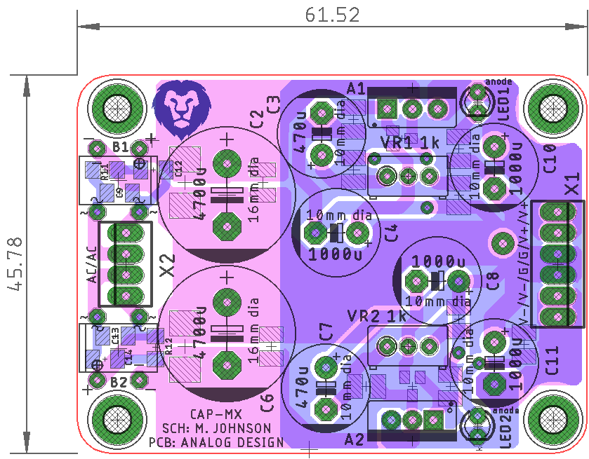
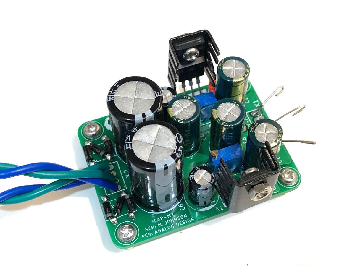
Gerbers posted, just order the PCBs and make it.
I use this all the time for headphone amps, preamps, etc. very simple and very low noise.
50/100/200Hz mains hum will be prevalent and might be tough to get rid of.
For a project like this, something like an external linear Class 2 wall wart with 12v or 24v powering an isolated DC-DC SMPS like a Meanwell or Tracon followed by TPS7A4XXX LDO’s will give you absolutely flat noise floor down to -120dB.
But if you like linear trafo based supplies, use a bigger box and put some distance and steel plates in between the trafo a amp PCBs.
There is a nice little PCB from Prasi that has the bridge with caps and dual rail cap Mx all in one for a very low noise PSU.
Juma's Easy-Peasy Capacitance Multiplier
Gerbers posted, just order the PCBs and make it.
I use this all the time for headphone amps, preamps, etc. very simple and very low noise.
- Status
- This old topic is closed. If you want to reopen this topic, contact a moderator using the "Report Post" button.
- Home
- Amplifiers
- Headphone Systems
- Minimalistic Buffered OpAmp HA