Hey all,
I have an imbalanced 10k potentiometer in my headphone amp and it's bothering me a lot. I know I could replace it with one of those loudly clicking resistor stepper pots but they are too big for the amp's enclosure and just not fun...
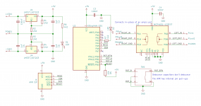
I'm just a hobbyist and came up with a circuit (see attachment) that will probably work as an add-on PCB but I'd love to hear opinions and suggestions, please. Maybe this is not terrible and I just need to add something, to avoid introducing any noise for example?
Notes:
I have an imbalanced 10k potentiometer in my headphone amp and it's bothering me a lot. I know I could replace it with one of those loudly clicking resistor stepper pots but they are too big for the amp's enclosure and just not fun...
I'm just a hobbyist and came up with a circuit (see attachment) that will probably work as an add-on PCB but I'd love to hear opinions and suggestions, please. Maybe this is not terrible and I just need to add something, to avoid introducing any noise for example?
Notes:
- The micro-controller will listen to the rotary encoder and control the U3 digipot accordingly
- Digipot's PxA, PxW and PxB pins will connect straight to the points of the amp's PCB where the pot is
- The 2 regulators will be connected to the amp's bridge rectifier before(?) the amp's own voltage regulators (a LM3x7 pair at ±15V)
The regs are there so that the incoming audio signal to the digipot is within digipot's supply voltage - Instead of the 2 regs I could bias incoming audio signal before it enters the digipot and then put a blocking cap on the output, but I'd like to avoid adding capacitors to the signal path
- MCP4651 digipot datasheet: https://ww1.microchip.com/downloads/en/DeviceDoc/22096b.pdf
Attachments
Last edited:
Channel tracking in pots is down to, well, pot luck even in some better-quality series. Did you try ordering a few to replace the existing one with the best candidate?
Are you possibly asking too much of the pot? Some lower quality parts may be giving up good balance around the -40 dB mark already, better specimens may to up to 50-60 dB at decent balance. If you're at 10 o'clock and balance still isn't OK, that's a bum pot. Below 9 o'clock, it is normal to encounter imbalance eventually. If you're down in that range, consider using a line-level attenuator if reducing amp gain is not an option.
1. Maximum input level will be limited to 5 Vpp = 1.768 Vrms at the very most. You sure that's enough? It's below typical CD player 0 dBFS level. Some (active) attenuation may be required.
2. Needs some input protection - few hundred ohms and reverse-biased (Schottky) diode to each rail.
3. No idea what sort of audio performance this part should have. Looks like your amp better have high input impedance, given wiper resistance nonlinearity.
3. You actually have a +/-2.5 V split supply there. Label and treat it accordingly - use the "real" PGND for bypass and all.
4. R2, R3 should get bypass caps; plus, more (electrolytic) output capacitance and protection diodes for both regulators.
5. Have an eye on resistor dissipation and add some frying resistors to take up some of the voltage in front if needed. Having to drop lots of voltage is annoyingly inefficient but short of using switch-mode converters there's not much you can do. Not a very power-hungry circuit anyway.
Maxim MAX5486 does all that logic in one chip. Power it with +/-2.7V and you don't need coupling caps.
MAX5486 Stereo Volume Control with Pushbutton Interface - Maxim
https://datasheets.maximintegrated.com/en/ds/MAX5486.pdf
Since the supply current is like 2mA, you could run run 5K resistors from your +/-15V supply to two 2.7V Zeners (or piles of 1N4148) and be done with that part.
MAX5486 Stereo Volume Control with Pushbutton Interface - Maxim
https://datasheets.maximintegrated.com/en/ds/MAX5486.pdf
Since the supply current is like 2mA, you could run run 5K resistors from your +/-15V supply to two 2.7V Zeners (or piles of 1N4148) and be done with that part.
Last edited:
The only thing even less efficient than a linear series pass regulator dropping a large amount of voltage is a shunt regulator doing the same... That said, we're only talking about a quarter watt if the zeners are sharing a total of 8 mA with the chip, and any series pass reg needs a minimum amount of current to work reasonably well (certainly a few mA for a '317... a 78L series part might be a better bet, otherwise a TL431 or compatible upgrade option would be a good upgrade from a plain zener).Since the supply current is like 2mA, you could run run 5K resistors from your +/-15V supply to two 2.7V Zeners (or piles of 1N4148) and be done with that part.
That MAX5486 is much more along the lines of what one would use here though. It's specifically designed for an audio application and spec'd accordingly. Still looks like about 1.5 Vrms is about the maximum it should ever be subjected to, 1 Vrms is uncritical.
Hmm. With a chip like that I would be tempted to connect its midpoint bias pin to pot ground, so as to eliminate(*) its additional noise contribution (about 2.2 µV, 20-20k, just like the buffer amps... I wonder how this correlates with the voltage noise density graph, which would seem to indicate well under 10 nV/sqrt(Hz) - they can't both be correct). This would require a totally floating +5V supply, given that the bias output can only take 3 kOhm || 100 pF. So maybe an 78L05 preceded by a 10-100 µF with symmetrical ~1 kOhm (1/4 W) droppers to +/-unregulated, kinda similar to what the OP was going to use?
The BIASCAP will also require some thought - I think this should be going to (real) PGND then, not VSS, or be left out altogether. (I think it's part of an R/RC dropper at bias amp input.)
Of course with a rather floating supply one has to be careful that asymmetric input signals can't throw things too far out of whack... a coupling cap may help.
*) "eliminate" in the sense of making it appear on the supplies instead, where PSRR would take care of it. 3 dB less noise is 3 dB less noise.
The question is, will 2.2 µV of noise be low enough? It's the kind of noise floor I'd like to have at the output of the amplifier, not the input. It obviously depends heavily upon headphones used and headphone amp gain - with some 102 dB/V home hi-fi cans you'd be getting away with 80 µV at the output easily, not so much when using 130 dB/V BA IEMs.
Then there's the question of how to best accommodate the required input levels. I guess you could just put extra resistance in series with the input as required, e.g. 39 kOhms for about a -6 dB reduction (which I reckon should have most consumer audio devices covered).
Last edited:
PRR and sgrossklass, I sincerely thank you both for the input. I'm reading and re-reading your posts ― still lots and lots for me to learn. Now I'm considering whether this is a worthy venture altogether ― my knowledge is insufficient to say the least. :-D let's stick to non-audio projects.
I designed a USB mixer using digital pots.
I made the mistake of not biasing the audio signal around 2.5 VDC into the pots and it sounded terrible.
I also didn't keep the audio and power supply grounds separate and that induced loads of hum.
On the next pcb revision I fixed those problems and ended up wit ha great little mixer.
I made the mistake of not biasing the audio signal around 2.5 VDC into the pots and it sounded terrible.
I also didn't keep the audio and power supply grounds separate and that induced loads of hum.
On the next pcb revision I fixed those problems and ended up wit ha great little mixer.
- Status
- This old topic is closed. If you want to reopen this topic, contact a moderator using the "Report Post" button.