Hi!
I hear with headphones a lot lately (250 Ohm Beyerdynamic DT880) and thought it would be time for a headphone amplifier as normal outputs do not generate enough output. However, thinking of integrating that amplifier in a full preamplifier in the future and wanting the PCB to be mounted vertically, I came up with a design myself.
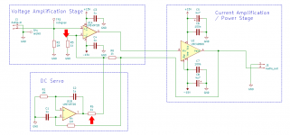
This thing is basically the datasheet application with some exceptions:
- As it will be a module, I omitted the potentiometer and replaced it with a 1M resistor to ground, as this value is used elsewhere on the PCB anyways.
- Instead of 4.7uF tantal, I use ceramic. 0.1uF stays.
Mechanically, I decided to do the following:
- There is no star ground, but rather a low impedance ground plane everywhere. What do you think about that? The return path for the output goes directly to the LME49600, so that should not introduce any problems (I hope)
- LME49600 will be heatsunk by the PCB. Hence the amount of vias. I think it is about as much as possible in the given form factor.
- All conections are via plugs. This might increase output impedance, but hey, it is a headphone amplifier and not a 2-Ohm car subwoofer amp.
- PCB is 99mm by 37.5mm. This will allow integration in a case with 40mm internal height.
- Biggest parts are 1000uF Caps with 15mm height (Panasonic FC). That allows stacking as well, but I think I go for vertical mounting as this should help convection a little.
- Mounting holes are 3.2mm for M3 screws, placed 30mm/75mm apart.
So, before I give the order, what do you think?
I hear with headphones a lot lately (250 Ohm Beyerdynamic DT880) and thought it would be time for a headphone amplifier as normal outputs do not generate enough output. However, thinking of integrating that amplifier in a full preamplifier in the future and wanting the PCB to be mounted vertically, I came up with a design myself.
This thing is basically the datasheet application with some exceptions:
- As it will be a module, I omitted the potentiometer and replaced it with a 1M resistor to ground, as this value is used elsewhere on the PCB anyways.
- Instead of 4.7uF tantal, I use ceramic. 0.1uF stays.
Mechanically, I decided to do the following:
- There is no star ground, but rather a low impedance ground plane everywhere. What do you think about that? The return path for the output goes directly to the LME49600, so that should not introduce any problems (I hope)
- LME49600 will be heatsunk by the PCB. Hence the amount of vias. I think it is about as much as possible in the given form factor.
- All conections are via plugs. This might increase output impedance, but hey, it is a headphone amplifier and not a 2-Ohm car subwoofer amp.
- PCB is 99mm by 37.5mm. This will allow integration in a case with 40mm internal height.
- Biggest parts are 1000uF Caps with 15mm height (Panasonic FC). That allows stacking as well, but I think I go for vertical mounting as this should help convection a little.
- Mounting holes are 3.2mm for M3 screws, placed 30mm/75mm apart.
So, before I give the order, what do you think?
Attachments
I think I would have made the offset current injection resistor ("R5") much, MUCH larger than the gain setting resistor ("R3").
I think I would have chosen the value of R5 using a design procedure with calculations such as
which gives, for Vsupply=15 and for R3=1000, R5 =approx= 166 Kohms
Notice that this will change the AC gain since R5 is now so large it does not participate in setting the AC gain. In the original schematic, R5 is so small that it does participate in setting the AC gain.
~

I think I would have chosen the value of R5 using a design procedure with calculations such as
- R5 =approx= (Vsupply - 5V) / (30mV / (R3||R6))
Notice that this will change the AC gain since R5 is now so large it does not participate in setting the AC gain. In the original schematic, R5 is so small that it does participate in setting the AC gain.
~
Attachments
Last edited:
Well seen, Mark Johnson! I actually just copied the schematic from TI, but an increase seems totally viable and I believe this might just be a typo from TI? Unlikely, but plausible. Gain would be roughly 2 then, which should be fine, but I would like to increase it back to 3, thus using a 470 Ohm resistor as R3. With 100k as injection resistor that would give me about 32mV of allowable offset until the servo reaches 10V and maybe saturates at some point. While having it in the schematic anyways, I will implement the 100k resistor as input resistor R2 as well.
00940, yes, input protection will be elsewhere. Do you mean a compensation cap parallel to R6 or some sort of single stage compensation? Seems to be a good idea though.
00940, yes, input protection will be elsewhere. Do you mean a compensation cap parallel to R6 or some sort of single stage compensation? Seems to be a good idea though.
Well seen, Mark Johnson! This might be a typo from TI, but then again such a thing is highly unlikely by them, yet plausible. However, I will make some changes in the schematic.
1: reduce R3 to 470 Ohm to maintain gain when increasing R5
2: increase R5 which will give about 32mV @10V Output from the Servo if i did not miscalculate
3: put an 0805 footprint parallel to leave the possibility for a compensation cap (good idea 00940, why didn't the guys at TI thought of something like that?)
4: As I use it anyway now, reduce R2 to 100k. Should make it less prone to pick up noise when unconnected.
RF protection will be elsewhere, yes.
I introduced two new parts now, but then again, I do not think I will ever mass produce this particular unit.
Best simulate that zobel... The values suggested are more suitable for a speaker amps than a headphones amp. We've been there before: best op amp for C'moy amp
An alternative to the DC servo would be to use a controlling opamp other than the LME49720. If the controlling opamp has the required DC specs of the complete amp, there's no need for the DC servo. OPA1611, OPA1642, and maybe even OPA1688 spring to mind. It'll require a bit more thought - especially for the OPA1611 - but it can be made to work. I used the OPA1611+LME49600 in my HP-1 (and made good use of my 2.9 GHz spectrum analyzer to track down spurious oscillations). Works great! I do recommend checking the amp with a >100 MHz oscilloscope or spectrum analyzer before putting it into service, though.
Tom
Tom
Well, a 100Mhz DSO is all I have at the moment. Also, I would like to stick to the datasheet application by TI as close as possible, so the DC servo and the op amp stays.
I will have a look if a Zobel network is necessary with my limited test gear, and if it is, add it to the socket as there will be wires anyway.
I just looked at your HP-1. Spectacular specs indeed! But I want a smaller design that is "good enough" - read: very good, but not bending-the-laws-of-physics-good. Yours might be 10 times less THD, but if mine is still 100 times lower than audible THD, then I do not really care. Still - respect to your design!
I will also build a quite simple power supply, mainly consisting of LM317/LM337 and a 15VA Transformer. Nothing spectacular, but enough to drive that headphone amplifier and some other small boards in a preamp as well. It will be noise reduced though (cap at the ADJ-PIN), so again - quite good, but not at the limit. The time to go to those technical limits has not come (yet?), but it might, for fun and/or as engineering exercise.
Regarding that supply and its transformer - I do not have it at hand yet, but I want to simulate it and need the effective resistance. Although it is not precise, I just use
(the idle voltage - the rated voltage) / rated current. That would be about 10 Ohms per winding. The transformer to be used has following specs:
18V - 0 - 18V @ 417mA, 22.2V open.
When designing for 250mA constant load and full-bridge rectification by 1N4007s, I get a minimum of 40V (give or take some mV) at the 2mF Cap when simulating with 10% less voltage (so, 40V @ 20 Ohms simulated transformer)
RMS current of the windings would be 395mA, close to 410mA when simulating with 10% more on the Mains. In this situation I get a little less than 3W Power dissipation for each regulator, so 20K/W heatsink or better shall be fine (found one with 13K/W that fits nicely).
Given the fact, that the headphone amplifier alone will be idling at 60mA (max quiescent current stated in datasheets, 18mA LME49600 plus 12mA LME49720) most of the time, I have something like 150mA to spare and still be very safe. That should be good for more than 15 dual op amps or so, so even a little bit energy-wasting stuff should be possible if needed.
Last edited:
According to this web page
Headphones sensitivity, impedance, required V/I/P, amplifier gain | Headphone Reviews and Discussion - Head-Fi.org
there are a couple of audiophile headphones that need more than 10V RMS input to play loud. That's +14.2V at a sinewave peak and -14.2V at a sinewave trough.
The LME49600 datasheet says that its max output voltage is 2.7 volts less than the supply rail, so if you want to drive these headphones you'll need a power supply of plus or minus seventeen volts at minimum.
Yes, I know. But how much will the difference be? Some 1 or 2 dB maybe, barely noticeable. However, I could easily change the PSU to about 16.7V output while still remaining more than 3V worst case for the regulator. As it costs nothing, that seems a logical thing to do.
The 15V will be enough though, or, if they aren't, neither are 17V. At the moment my problem is limited headroom / not enough volume out of the laptop output, which is 2Vrms or so at max. This amp here will provide 8 or 9Vrms happily into my headphones, increasing power by a factor of 16-20.
Again: I am not trying to build the best headphone amplifier ever made, just one that will suit 95% of any needs I or any person will ever have to such a device. Keep it small and (relatively) simple.
OT: It's the same with Power amps for speakers. 100W will give you 3dB more Headroom than 50W. Most people just need a fraction of this. I was quite happy with a 1W SE Triode amp I built a while ago, which was more than adequate at low listening levels. Just switched back because when hearing loud (I mean, LOUD) it was not up to the task. 10W might do it though. Anyway, those last couple of volts don't make much of a difference, but I will keep them as they are basically for free in my current design. So, thank you again!
Well, a 100Mhz DSO is all I have at the moment. Also, I would like to stick to the datasheet application by TI as close as possible, so the DC servo and the op amp stays.
Fair enough. I would encourage you to use a different opamp for the DC servo, though. The "few mV" offset of the LME49720 isn't fantastic. You could use something like the OPA2277 or even OPA1688 if memory serves without impacting the stability of the amp.
I just looked at your HP-1. Spectacular specs indeed! But I want a smaller design that is "good enough" - read: very good, but not bending-the-laws-of-physics-good. Yours might be 10 times less THD, but if mine is still 100 times lower than audible THD, then I do not really care. Still - respect to your design!
Thank you. I appreciate it. The HP-1 is indeed good. Your approach seems perfectly reasonable to me. Just keep in mind that above all, the amp should be stable.
Regarding that supply and its transformer - I do not have it at hand yet, but I want to simulate it and need the effective resistance. Although it is not precise, I just use
(the idle voltage - the rated voltage) / rated current. That would be about 10 Ohms per winding. The transformer to be used has following specs:
18V - 0 - 18V @ 417mA, 22.2V open.
For supply simulations I find PSUD2 to be quite useful. I'd model the load current as a constant current.
there are a couple of audiophile headphones that need more than 10V RMS input to play loud. That's +14.2V at a sinewave peak and -14.2V at a sinewave trough.
True. The HifiMan HE-6 springs to mind as the worst offender among them. If you don't own those phones, don't plan to, or don't play that loud anyway, you're safe to ignore them, in particular if you're building this amp for your personal enjoyment rather than commercial production. The LME49600 will blow most headphones apart if given the chance.
The LME49600 datasheet says that its max output voltage is 2.7 volts less than the supply rail, so if you want to drive these headphones you'll need a power supply of plus or minus seventeen volts at minimum.
The data sheet also says that its output current is limited to 250 mA (typ.), so a single LME49600 couldn't drive the HE-6 to the target 110 dB SPL if it tried. If that's your target, you should probably look for other solutions.
Tom
Calculator broken? ")
10 V, 159 mA RMS = 14.1 V, 225 mA peak.
At 150 mA output current, the LME49600 is spec'ed at 3.5 V Vce drop, worst case. The voltage drop increases with increasing output current and there's no word on how much that drop is at 225 mA. At ±18 V, I doubt the LME49600 will get all the way to 14.1 V peak, but it'll be close.
Whomever wrote the section of the spec table that deals with output swing got themselves rather confused it looks like. At least two pairs of the typical and worst case numbers are swapped.
Tom
Yes it seems the pragmatic approach is to use ±18V supplies and two LME49600s working in parallel. You get double the output current, and the parallel connection probably reduces distortion too, as it does in all-discrete power amps: Cordell's textbook on Charts 3.6 thru 3.8 (pp. 69-73).
Wow, there have been quite some replies! Let's see if I can address them all.
I like the clipping LED But I will keep it simple in this particular amplifier, so... maybe the next one.
Different op amp for the DC servo - will certainly be better, but I do not wish to implement another part in this design. Actually, the LM49720 is just used for its high linearity and low distortion, and to keep the other half busy it is used as a Servo. Results will not be stellar, but certainly better than without, and very probably "good enough". I appreciate this tip though and definitely will measure the results of the unit. If it is too much, I might respin the board and include a precision op amp.
I actually use PSUD2 for my designs. Quite accurate and gives a very good idea how much power you get out of the supply without damaging anything.
Short circuit output current is even 490mA, but I doubt I will ever come in this region. I have a demanding, but not very demanding pair of headphones.
I think I just have to give it a go then and let the chinese manufacture the PCBs for this amp. There will be quite a long way to the finished unit though. Or I start with this, the power supply and an RF protection soldered to the RCA jacks for a start. Can add the rest later.
Thanks again for all the replies!
I like the clipping LED
But I will keep it simple in this particular amplifier, so... maybe the next one.Different op amp for the DC servo - will certainly be better, but I do not wish to implement another part in this design. Actually, the LM49720 is just used for its high linearity and low distortion, and to keep the other half busy it is used as a Servo. Results will not be stellar, but certainly better than without, and very probably "good enough". I appreciate this tip though and definitely will measure the results of the unit. If it is too much, I might respin the board and include a precision op amp.
I actually use PSUD2 for my designs. Quite accurate and gives a very good idea how much power you get out of the supply without damaging anything.
Short circuit output current is even 490mA, but I doubt I will ever come in this region. I have a demanding, but not very demanding pair of headphones.
I think I just have to give it a go then and let the chinese manufacture the PCBs for this amp. There will be quite a long way to the finished unit though. Or I start with this, the power supply and an RF protection soldered to the RCA jacks for a start. Can add the rest later.
Thanks again for all the replies!
- Status
- This old topic is closed. If you want to reopen this topic, contact a moderator using the "Report Post" button.
- Home
- Amplifiers
- Headphone Systems
- Small form factor LME49600 approach