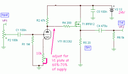
Hi, this is the schematic of the amp, the heater actually has its own 6v supply not 24v:

Basically it is xrk971's Class A Desktop amp with the BF862 JFET replaced with a tube based on this schematic
I wanted to see how well it would work without changing a single component. the JFET was removed and a R102/103 (100K) is connected to supply instead of ground as the plate resistor . it does work but the bass specifically is extremely distorted, Im wondering what might be the cause of this and how easily it could be fixed.
There is no coupling capacitor before the tubes, since it's affecting bass I thought tubes might be more sensitive to DC than solid state and this could be the cause but there is only like 2mv dc from the source
Last edited:
I suspect the reason for extreme bass distortion is simply its clipping on positive going signals. Your chosen bias point for the MOSFET (22k/1.1k) needs to be much closer to mid-rail (12V). Also the paralleled impedance of those two resistors is too low, how about making them 220k/220k?
I can see the problem now, thanks.I suspect the reason for extreme bass distortion is simply its clipping on positive going signals. Your chosen bias point for the MOSFET (22k/1.1k) needs to be much closer to mid-rail (12V). Also the paralleled impedance of those two resistors is too low, how about making them 220k/220k?
it looks like the original JFET was for biasing and was a better solution than the biasing resistors in tube amp schematic,
So is the tube just there to add some nice distortion or does actually it have a use?
btw supply is actually 20V (24v input to cap multiplier and CRC filter drops to to 20V)
I'm unfamiliar with tubes but it does look to me to be providing some gain - the FET is only a buffer (i.e. unity gain).
With a 20V supply I'd suggest holding the gate around 14V to allow ~4V for gate turn-on. You don't really want the parallel resistance of the bias network to be lower than your anode resistor (100k). Fortunately with a FET you can go quite high. Try 240k top and 560k bottom.
With a 20V supply I'd suggest holding the gate around 14V to allow ~4V for gate turn-on. You don't really want the parallel resistance of the bias network to be lower than your anode resistor (100k). Fortunately with a FET you can go quite high. Try 240k top and 560k bottom.
using those resistor value for biasing worked and just replacing JFET worked too but probably best to avoid having 2 gain stage and stick with resistors.
reducing 100k did help also for SQ, gain is still extremely high though
the remaining issue is loud buzzing/EMI, the tubes are causing it, disconnecting the source didnt help.
issues aside the sound is a bit lo-fi, gimmicky, switching to ECC86 as suggested might be step towards a more serious tube sound
- Status
- This old topic is closed. If you want to reopen this topic, contact a moderator using the "Report Post" button.
- Home
- Amplifiers
- Headphone Systems
- any obvious reason for extreme bass distortion with this schematic?
