Could you help with the schematic? Most probably it was deleted to protect the Blue Hawaii project, but honestly i'd like to see the originalI don't own a Stax but if I did, it would be the 009s with a Stax DIY SRM-T2.
The ultimate DIY? A Stax SRM-T2! - Do It Yourself - www.Head-Case.org
")
Could you help with the schematic? Most probably it was deleted to protect the Blue Hawaii project, but honestly i'd like to see the original
This is the funniest thing I've read. Everything Kevin did was published.
Attachments
Thank you very much Sir!This is the funniest thing I've read. Everything Kevin did was published.
Thinking About Building This Circuit - Have a few questions
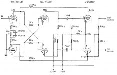
"Stax SRX" schematic --> Electrostatic Headphones Amps
I had built this SRX and "it made some fine music";
not very difficult to build, if you've done some diy with vacuum tubes
(but after all I dismantled it, because the oscilloscope traces showed a large unbalance between the two signals from the phase splitter (I think this setup is called "Van Scoyoc" - it could be that I was just not measuring correctly, since I found out much later that the probe may influence the signal and you need to compensate for this...)
I'd like to build this circuit but the Schematic only shows one channel with a differential output ? I'm assuming I'd have to build this circuit twice tat would connect to four of the five pins. on the headphone connector. Where does the 5th wire on my headphones connect to ?
Attachments
Hi rajugsw,
indeed the schematic is one channel.
Sorry to be outright, but based on your questions, I suggest that you do some research about Stax amplifiers. These circuits involve dangerous voltages, even more than usual audio, and extra precautions must be taken.
Just quickly (you'll find it explained better than what I can do):
Stax headphones are indeed driven "differentially", so the schematic has a "plus" and a "minus" output for one channel.
The fifth connection to the headphones is the so called "bias", a constant voltage of about +580V DC.
The circuit for the bias supply is not represented in this schematic.
You'll need one bias supply for one headphone, going to both right and left "earspeaker"; you will not need two of those circuits.
The circuit for the amplifier power supply is also not represented in the schematic.
Cheers,
pilli
_
Hello everybody ,
I'm interested to build my own tube direct Drive amplifier.
I Wonder what are the troubles with output capacitors ?
Please
Electrostatic headphones are essentially a capacitive load, and are hard enough for a high voltage amplifier to drive directly. Adding additional output capacitance (series capacitors) just makes driving the load worse.
Last edited:
Electrostatic headphones are essentially a capacitive load, and are hard enough for a high voltage amplifier to drive directly. Adding additional output capacitance (series capacitors) just makes driving the load worse.
Thanks for reply.
But in fact the value of a 0,01uf output capacitor in serie with a 150pf stator is vert near of the capacitance of a 150pf stator , isn't it? (Value IS=147,8pf)
The All-triode direct-drive tube amp Gilmore got output capacitors (2uf).
Neil Pollock and Philip D. Harvey too.
So is there another raison ? Or i'm wrong ?
I’ve built his KGST, Carbon, Grounded Grid and Current Feedback electrostatic headphone amps, and don’t recall a schematic to a Keven Gilmore designed electrostatic amp with output capacitors. Tube or SS. His tend to be fully differential direct coupled outputs. His all tube Megatron has interstate coupling caps, but it’s outputs are direct coupled (no capacitors).
I’m not following the figures you are posting. Can you post a circuit of what you have in mind?
Semisouth JFET's: What are they good for?
Just use a good one, e.g. WIMA FKP1 or FKP4.
The headphone itself is also a cap.
Patrick
Just use a good one, e.g. WIMA FKP1 or FKP4.
The headphone itself is also a cap.
Patrick
> don’t recall a schematic to a Keven Gilmore designed electrostatic amp with output capacitors
https://headwizememorial.wordpress....ps-for-electrostatic-and-electret-headphones/
Patrick
https://headwizememorial.wordpress....ps-for-electrostatic-and-electret-headphones/
Patrick
> don’t recall a schematic to a Keven Gilmore designed electrostatic amp with output capacitors
All-Triode Direct-Drive Tube Amps for Electrostatic and Electret Headphones. – HeadWize Memorial
Patrick
Thanks Patrick.
Way before my time at Head Case. I see you have focused on Figure 1, while I’ve been more familiar with his later direct coupled Figure 2 designs.
Why would the outputs have capacitors on the earlier design?
Last edited:
C6,C9:2uf.
Go ahead and build your amp per Figure 1, the AC coupled design.
I know only from building the later Gilmore direct coupled designs.
There is a simple reason to use DC coupled output, or rather dual (symmetrical) voltage power supply.
If you wish to have say +/-350V output per phase, you would need a +/-380V PSU, or a bit higher.
But for a single voltage PSU and hence capacitor coupled output, you would need to go to +700V or more.
PSU for such high voltage is not trivial, and it is also getting dangerous and hazardous.
Electrostatic Headphone Amplifier & IMC for 300B
Patrick
Go ahead and build your amp per Figure 1, the AC coupled design.
I know only from building the later Gilmore direct coupled designs.
Hello.
Thanks for reply and encouragements.
The design seems very difficult for me.
I want to do simple.
The amplifier for stax from Patrick is at my level.
(Or Philips D.Harvey).3 tubes per chanel is enough.
So:
2 output tubes and a phase inverter amplifier per chanel.
No Feedback loop.
If you use google translate to read that webpage, you will realise he did not build the default Stax circuit.
This is the one he built instead. With feedback loop.
http://home.q08.itscom.net/ryo-tai/amp/stax5.jpg
Maybe this is more interesting for you :
http://www.dddac.de/files/auridux22.pdf
AURIDUX, a directly coupled Stax Electrostatic Headphone Tube Amplifier
He is also Dutch.
Patrick
This is the one he built instead. With feedback loop.
http://home.q08.itscom.net/ryo-tai/amp/stax5.jpg
Maybe this is more interesting for you :
http://www.dddac.de/files/auridux22.pdf
AURIDUX, a directly coupled Stax Electrostatic Headphone Tube Amplifier
He is also Dutch.
Patrick
Thanks for your schematics.If you use google translate to read that webpage, you will realise he did not build the default Stax circuit.
This is the one he built instead. With feedback loop.
http://home.q08.itscom.net/ryo-tai/amp/stax5.jpg
Maybe this is more interesting for you :
http://www.dddac.de/files/auridux22.pdf
AURIDUX, a directly coupled Stax Electrostatic Headphone Tube Amplifier
He is also Dutch.
Patrick
Auridux is very intéressant. Mu follower at output stage bring a Big voltage swing.
I'm now waiting for adhésif mylar tape to re-wind my power transformer.Ot will be around 150 va.
I want to have 200 250 300 600 v at secondary in one coil.
No place for more coils.
And After i will test some tubes.
Regards
- Home
- Amplifiers
- Headphone Systems
- What DIY Amps are available for Stax?