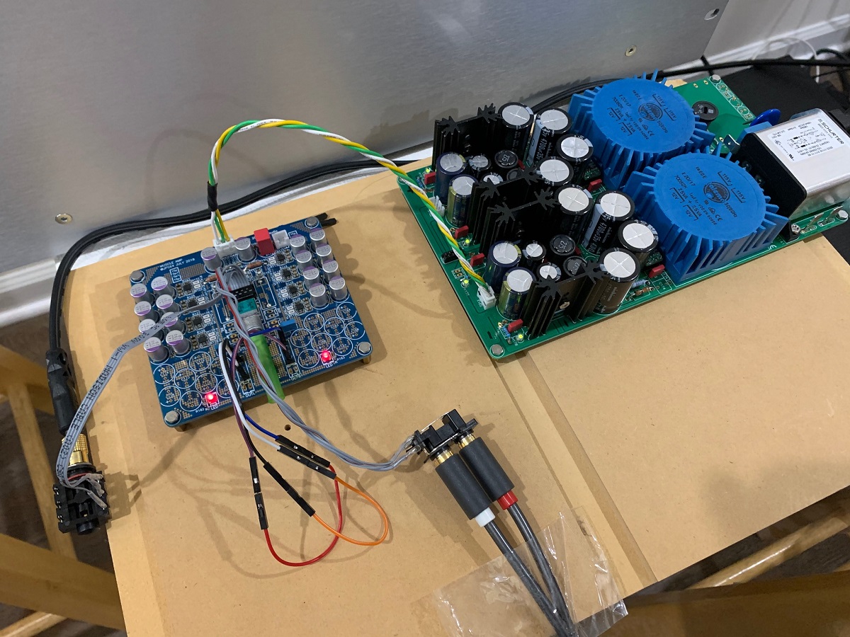
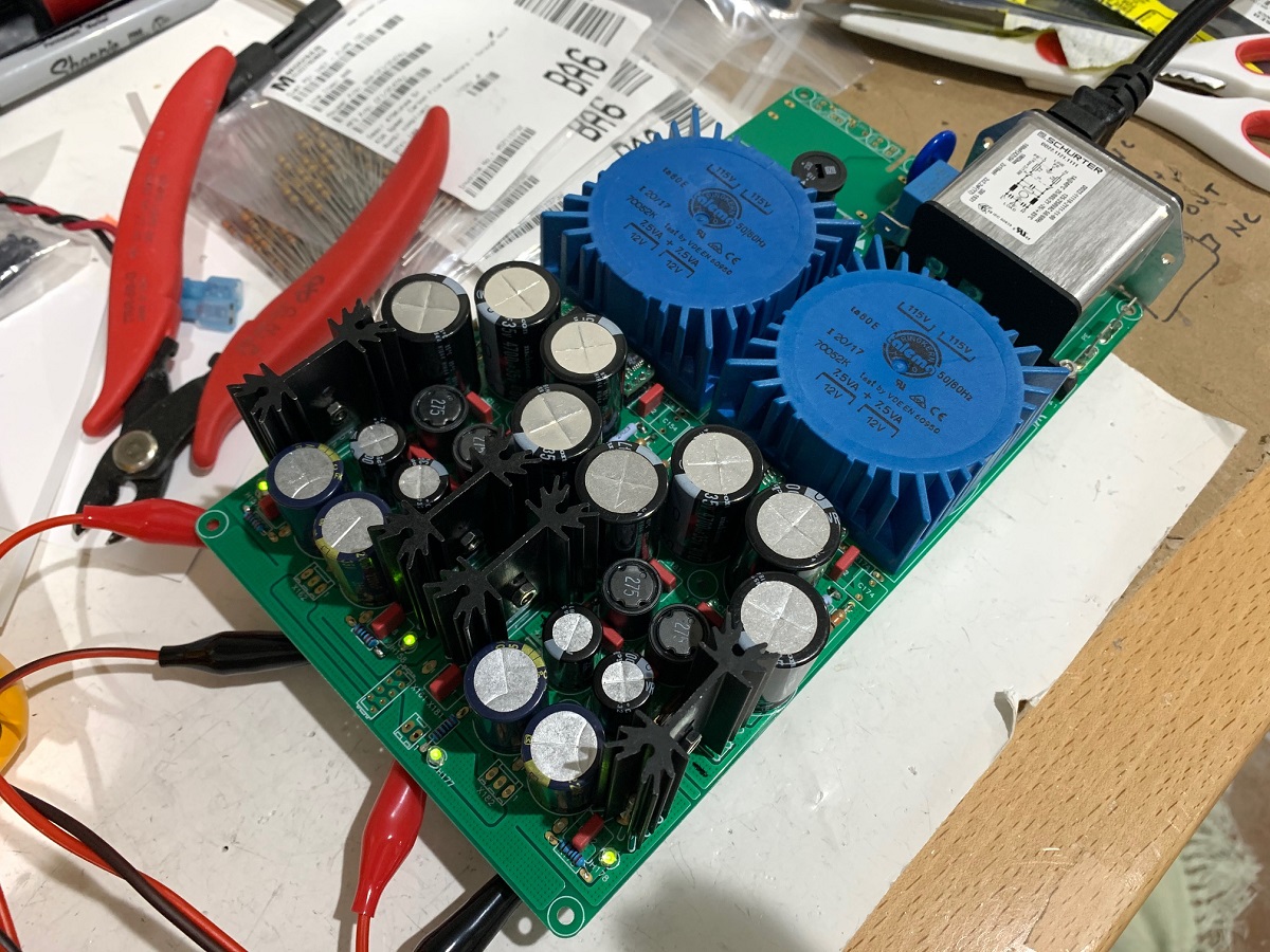
Testing out a new linear psu ideally suited for high end headphone amps or preamps. It’s a dual monoblock design with linear transformer followed by LT4320 active bridges to eliminate diode bridge switching noise, then a CRCLC filter, then TPS7A4XXX ultra low noise LDO regulators. I am testing it out with the parallel 8x OPA1622 headphone amp. Sounds very very good. Super quiet.
The YARRA Preamplifier/HPA for Melbourne DB Group Buy
The YARRA Preamplifier/HPA for Melbourne DB Group Buy
Hi - XRK , very nice design, it looks like something that would be challenging but fun to build. Have you seen Blue circles NSL Op-Amp Amplifier? He designed it using 288 Op Amps for 28 watts, he said it takes him about 15 days to wire all 288 Op-Amps. There is a short review if anyone is interested, I'll post the link below .... the reviewer ended up comparing it to a - $130,000 amplifier he was working with at the time, and seemed to like it better - LOL
I've been looking for a design like this since I first saw Blue Circles design, I actually tried a couple of times to start a design thread for the idea but since I'm a newbe I didn't know enough to get people excited about the idea I guess -")
-- I was wondering if there is a way to design it with the option to stack the boards to have a few more watts??? -- Just curious
Here's the Link --
Blue Circle Audio NSL Stereo Amplifier - The Audio Beat - www.TheAudioBeat.com
I've been looking for a design like this since I first saw Blue Circles design, I actually tried a couple of times to start a design thread for the idea but since I'm a newbe I didn't know enough to get people excited about the idea I guess -
-- I was wondering if there is a way to design it with the option to stack the boards to have a few more watts??? -- Just curious
Here's the Link --
Blue Circle Audio NSL Stereo Amplifier - The Audio Beat - www.TheAudioBeat.com
If I did this right, the 2k2 (R1) and 6k8 (R2) presents a 1660R impedance to the negative input, so we need to match this impedance on the positive input. However, when accounting for the 47k (R3) to ground, a value of 1720R for R4 is needed to present a 1660R impedance to the positive inout. The sim result was unchanged. I tried minimizing the impedance by making the feedback 680R and the ground shunt 220R, this effectively makes the 47k unimportant and a 166R R4 was used. The sim for this actually showed distortion increasing from 0.000063% to 0.000068%. Doing this also makes the output effectively driving a 166R load under full power - quite a bit of dissipation and a much larger power resistor would be needed. I think I will keep it at 6k8 and 2k2 with 1720R R4.
Thank you for sharing the project, I learned a lot. Could you please give me some tips or point to some reference about how C1 was chosen? I see C1 as local feedback for U1 and R2 as a global feedback path. I searched for composite amplifiers, nested feedback and did not find about this local loop capacitor C1,how to choose it and evaluate performance and stability. I also would like to know about the benefits of global feedback instead of one loop for gain stage and a separate loop for buffer stage. Thanks
Here is an interesting surprise, I replaced the LME47720, the supposedly "king of the low THD" opamps in TI's arsenal, with the lowly OPA1688 (which is also serving as the buffer).
Here is the schematic:
If we give the power supply rails lots of caps so that the impedance is infinitessimally low, here is what we can get for 8Vpp into 8ohms:
I think that's PPB (part per billion) HD components.
The graph is unusual too (I have never simulated anything that has zero features before):
So I took it to 28Vpp into 32ohms, that's 2.5wrms nd enough juice to drive the most inefficient planar headphones, here are the FFT components:
Here is the time series:
Here is the FFT:
Now, that's a "Muscle Amp".
Now, that's a .subckt .model
- Status
- This old topic is closed. If you want to reopen this topic, contact a moderator using the "Report Post" button.