Personally I have 32 Ohms headphones. When impedance is 32 Ohm and lower, there is really no need of voltage gain. This is why I suggest a buffer, a voltage follower.
My circuit is such a follower.
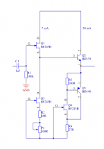
There is no feedback loop. It is only current gain. P1 is used to set the output at 0.0 volt. For no DC-offset.
The output is one current source. There is the possibility to increase the current in output stage. By adjusting the R4 resistor. For my 32 Ohms headphones it is not necessary. 50mA is enough. But we can use for example MJE15030-31 in the output.
BF245B was chosen for the availability. And low price. Can be used for 30V. So, maximal power supply should be 2x15VDC. Regulated is recommended. For example use LM317T/LM337T.
My circuit is such a follower.
There is no feedback loop. It is only current gain. P1 is used to set the output at 0.0 volt. For no DC-offset.
The output is one current source. There is the possibility to increase the current in output stage. By adjusting the R4 resistor. For my 32 Ohms headphones it is not necessary. 50mA is enough. But we can use for example MJE15030-31 in the output.
BF245B was chosen for the availability. And low price. Can be used for 30V. So, maximal power supply should be 2x15VDC. Regulated is recommended. For example use LM317T/LM337T.
Attachments
Hi Lineup,
I sim’d this circuit in LTSpice and it has large 12v offset at output. Although done with BF862, I don’t think that should change DC setpoints that much. Thd AC performance looks nice though as expected for a SE Class A design. Have you run your own sim yet?
I sim’d this circuit in LTSpice and it has large 12v offset at output. Although done with BF862, I don’t think that should change DC setpoints that much. Thd AC performance looks nice though as expected for a SE Class A design. Have you run your own sim yet?
Last edited:
You should use a dual supply.Hi Lineup,
I sim’d this circuit in LTSpice and it has large 12v offset at output. Although done with BF862, I don’t think that should change DC setpoints that much. Thd AC performance looks nice though as expected for a SE Class A design. Have you run your own sim yet?
+/-12 or +/-15 Volt.
I can not do sim.
For being a voltage follower, we can expect rather low THD.
As there is no voltage gain.
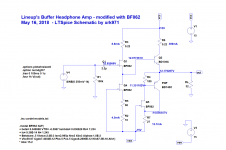
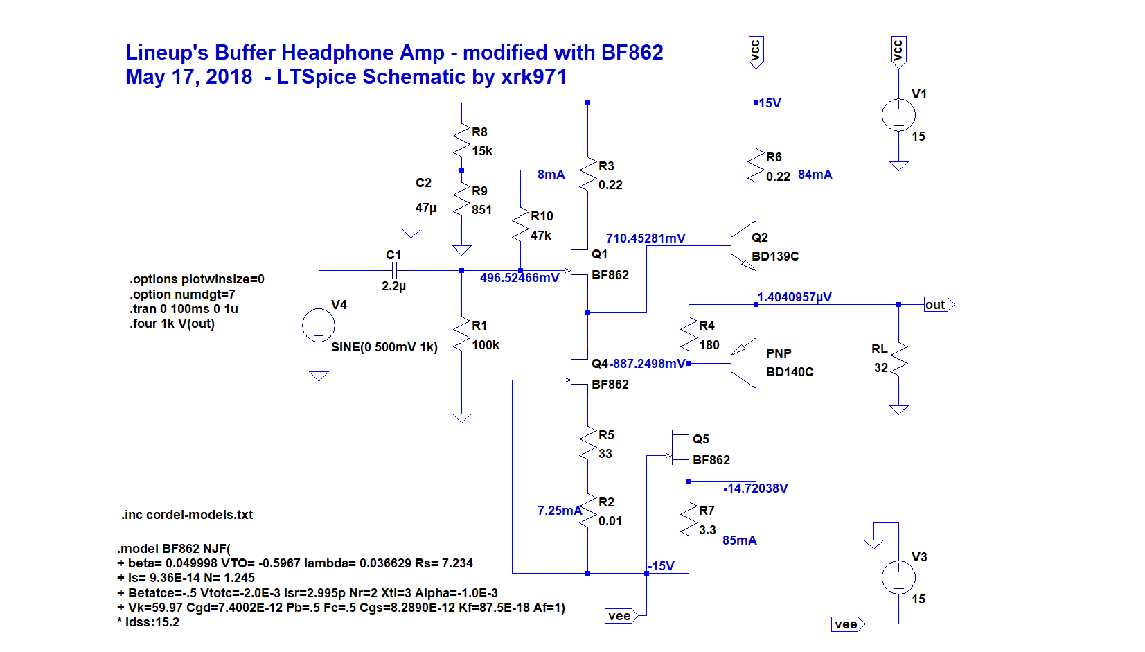
LTSpice Schematic
Hi Lineup,
Here is the 12v DC offset at the output that I was talking about. Changing the pot doesn't do anything. I think you need to apply a voltage divider from the +ve rail (filtered with say 47uF) and apply correct bias to Gate of Q1 in order to get the correct bias on the input and output stage.
I don't think change in type of JFET changes the fundamental DC setpoint behavior.

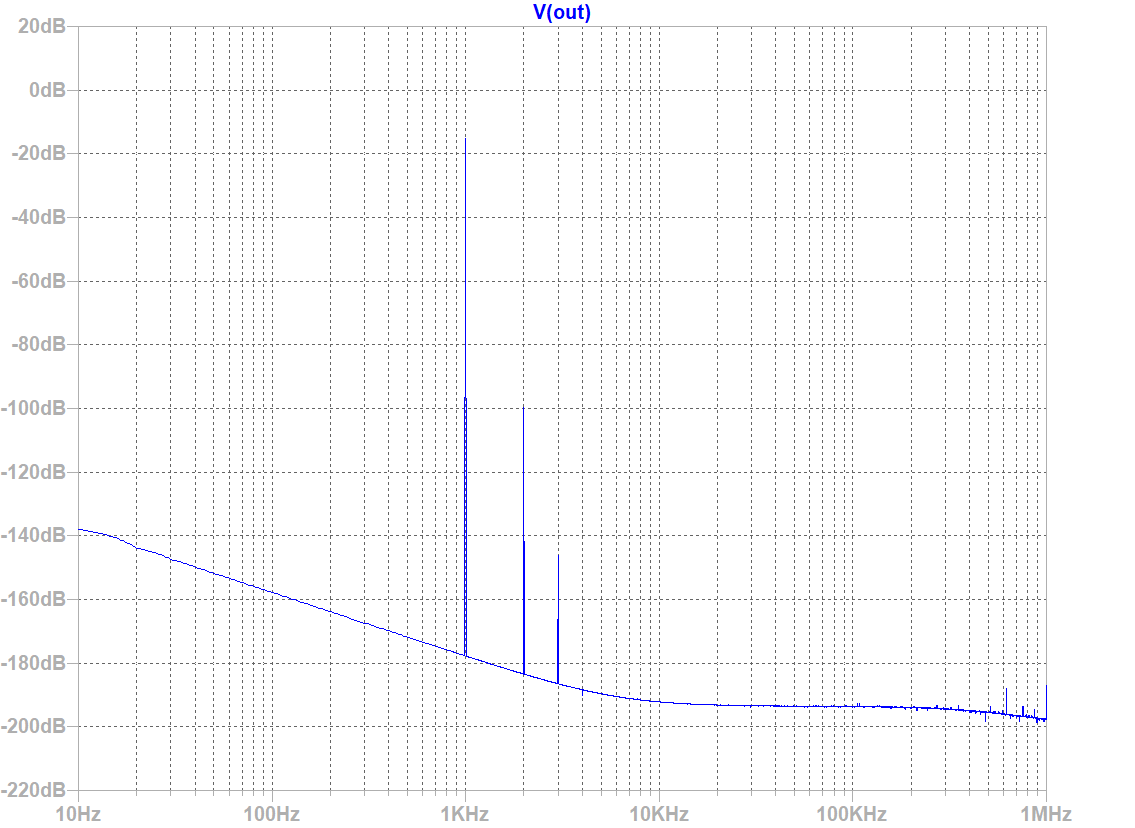
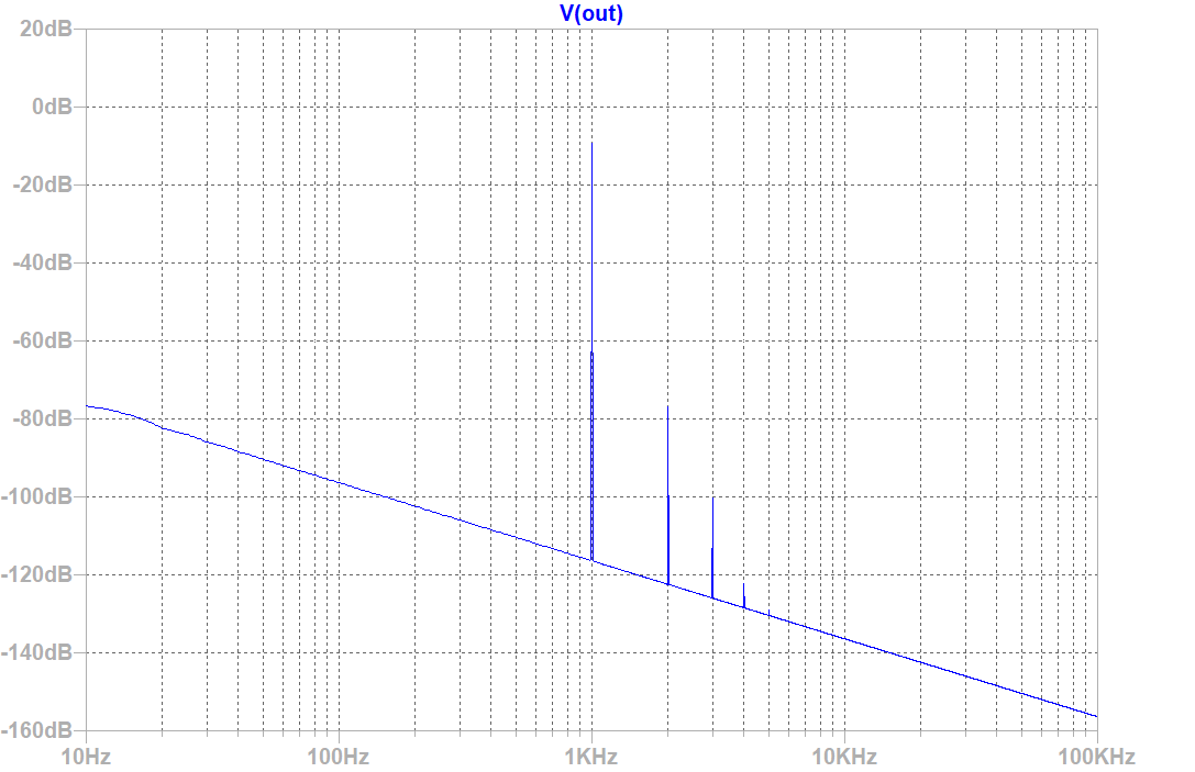
Even with DC, offset, the THD is indeed low and the profile is nice H2 and descending higher orders:
FFT with 500mVpp into 32ohms:
Hi Lineup,
Here is the 12v DC offset at the output that I was talking about. Changing the pot doesn't do anything. I think you need to apply a voltage divider from the +ve rail (filtered with say 47uF) and apply correct bias to Gate of Q1 in order to get the correct bias on the input and output stage.
I don't think change in type of JFET changes the fundamental DC setpoint behavior.
Even with DC, offset, the THD is indeed low and the profile is nice H2 and descending higher orders:
Harmonic Frequency Fourier Normalized Phase Normalized
Number [Hz] Component Component [degree] Phase [deg]
1 1.000e+03 2.431e-01 1.000e+00 -0.01° 0.00°
2 2.000e+03 1.458e-05 5.995e-05 93.38° 93.39°
3 3.000e+03 6.961e-08 2.863e-07 9.07° 9.08°
4 4.000e+03 1.921e-10 7.901e-10 -168.65° -168.65°
5 5.000e+03 1.575e-10 6.479e-10 -178.44° -178.44°
6 6.000e+03 5.456e-11 2.244e-10 -177.89° -177.88°
7 7.000e+03 2.971e-11 1.222e-10 -2.57° -2.57°
8 8.000e+03 1.031e-10 4.239e-10 -0.33° -0.33°
9 9.000e+03 1.693e-10 6.962e-10 0.09° 0.09°
Total Harmonic Distortion: 0.005995%(0.005854%)
FFT with 500mVpp into 32ohms:
Attachments
Last edited:
Changing that error did not fix problem in that the circuit clipped badly on negative side. The only way to fix was to add a voltage divider in order to bias the gate of Q1 properly. This sets the DC offset as well as sets the bias current in Q1. With this, the performance for 1vpp gives THD of 0.04% which is no better than my circuits which use a plain resistor vs CCS's.
New schematic:
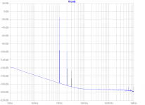
FFT:
Distortion driving 32ohm load 1vpp:
But, driving 270ohm load 1vpp give very low THD of 0.0008%:
This would indeed sound exceptionally clean with higher impedance phones - but they need more voltage gain, so a preamp is needed.
Note, I moved the R1 100k to the left of the cap C1 and it did not make any difference (THD) other than reset the pot R9 to 590R to zero DC offset.
With 6vpp into 270ohms, I was still getting THD of 0.005%, an excellent follower.
New schematic:
FFT:
Distortion driving 32ohm load 1vpp:
Harmonic Frequency Fourier Normalized Phase Normalized
Number [Hz] Component Component [degree] Phase [deg]
1 1.000e+03 4.863e-01 1.000e+00 0.13° 0.00°
2 2.000e+03 2.011e-04 4.135e-04 -89.86° -89.98°
3 3.000e+03 1.390e-05 2.858e-05 0.45° 0.32°
4 4.000e+03 9.866e-07 2.029e-06 104.66° 104.53°
5 5.000e+03 2.621e-07 5.390e-07 -179.82° -179.95°
6 6.000e+03 1.605e-07 3.300e-07 -178.12° -178.25°
7 7.000e+03 1.370e-07 2.817e-07 -180.00° -180.12°
8 8.000e+03 1.201e-07 2.469e-07 179.99° 179.86°
9 9.000e+03 1.066e-07 2.192e-07 -179.99° -180.12°
Total Harmonic Distortion: 0.041454%(0.041434%)
But, driving 270ohm load 1vpp give very low THD of 0.0008%:
Harmonic Frequency Fourier Normalized Phase Normalized
Number [Hz] Component Component [degree] Phase [deg]
1 1.000e+03 4.955e-01 1.000e+00 0.09° 0.00°
2 2.000e+03 4.216e-06 8.509e-06 89.14° 89.06°
3 3.000e+03 9.456e-09 1.908e-08 169.62° 169.54°
4 4.000e+03 9.982e-08 2.015e-07 179.83° 179.74°
5 5.000e+03 7.973e-08 1.609e-07 -179.98° -180.07°
6 6.000e+03 6.628e-08 1.338e-07 -179.99° -180.07°
7 7.000e+03 5.666e-08 1.144e-07 -179.99° -180.08°
8 8.000e+03 4.942e-08 9.974e-08 -179.99° -180.08°
9 9.000e+03 4.377e-08 8.834e-08 -180.00° -180.08°
Total Harmonic Distortion: 0.000852%(0.000000%)
This would indeed sound exceptionally clean with higher impedance phones - but they need more voltage gain, so a preamp is needed.
Note, I moved the R1 100k to the left of the cap C1 and it did not make any difference (THD) other than reset the pot R9 to 590R to zero DC offset.
With 6vpp into 270ohms, I was still getting THD of 0.005%, an excellent follower.
Attachments
Last edited:
That is correct.Looks like there is, indeed, a wiring error. Lineup's original circuit has what you call R1 connected directly to Q1's gate. Seems to me the input cap is unnecessary, unless one is worried about DC offset from the source.
I put this only to protect from sources with offset.
My idea is working.
But I am sorry to say it does not work good.
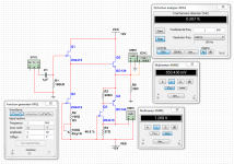
My testing shows 1Vpeak gives 0.92Vpeak out. With load 32 Ohm.
But the THD distortion is not nice - THD 0.287% is not acceptable.
I dont know how you, xrk971, have done your testing.
But I think my numbers are closer to the truth.
Unfortunately Multisim SPICE for BF245 is not working.
So I did my testing with 2N4416 JFET.
But I am sorry to say it does not work good.
My testing shows 1Vpeak gives 0.92Vpeak out. With load 32 Ohm.
But the THD distortion is not nice - THD 0.287% is not acceptable.
I dont know how you, xrk971, have done your testing.
But I think my numbers are closer to the truth.
Unfortunately Multisim SPICE for BF245 is not working.
So I did my testing with 2N4416 JFET.
Attachments
Nice circuit line-up. Very similar to the LH0033 buffer internal circuit!
Can I ask why the limitation of 50mA?
one of my earlier headphone amp testing circuits also uses BD139/140, diode biased into class AB and develops more current than 50mA, from memory about 2 Watts into 8 Ohm.
Great stuff here, I myself have been a little inspired by EUVL Can and recreation of the LH0033 internal circuit. I'll have to try this circuit out as another option")
Can I ask why the limitation of 50mA?
one of my earlier headphone amp testing circuits also uses BD139/140, diode biased into class AB and develops more current than 50mA, from memory about 2 Watts into 8 Ohm.
Great stuff here, I myself have been a little inspired by EUVL Can and recreation of the LH0033 internal circuit. I'll have to try this circuit out as another option
The 50mA is because I have 32 Ohms headphones.
Of course the current in outputstage can be increased.
8 Ohms headphones needs lot of more current.
Then we have the 330/600 Ohm.
They need voltage, so can not do with a plain buffer.
For 8-32 Ohms there is no need for voltage amplification.
I am now working on a 3 transistor buffer with JFET input and feedback.
And the output transistor is BD139 resistor biased with 50mA.
Hmmm, I might add a current source to this.
For this I get now like THD 0.002%.
Compared to the buffer above which is THD 0.287%
Sounds like you have a clear plan of action.
I only wish I had simulation ability or THD measurement so I could judge the output numerically
I'm stuck with looking at a scope trace, judging the onset of clipping, and then backing off input to give a margin of safety.
Agreed with Sennheisers etc, the current requirements are so small, I'm tempted to build a dedicated amp with just a couple of LME49860. If I feel brave I may try something discrete...I have a box of bc441, bc107 and a like. I may even have a couple of FETs in there if I'm lucky.
...My testing shows 1Vpeak gives 0.92Vpeak out. With load 32 Ohm.
But the THD distortion is not nice - THD 0.287% is not acceptable.....
How bad does 0.3% THD really sound?
47mA peak in 32 Ohms is 1.5V peak 1.06Vrms at clipping.
The current is swinging from near-zero to 94mA.
At this point, a collector-loaded amp would be near 26% THD.
Emitter follower has NFB and THD will be lower. 47mA suggests re (hie) is about 0.55 Ohms. Relative to load, about 57:1 NFB. So 26%/57 is about 0.45% THD. Your level is about 2/3rd of clipping, so THD may be ~~2/3rd, about 0.3%.
If I can back-figure your results on a matchbook, then you can look-at how I did that and figure what to change for higher performance.
BTW: that complex current source could be replaced with a 255 Ohm resistor, very little difference when loaded with 32 Ohms.
Attachments
Last edited:
- Home
- Amplifiers
- Headphone Systems
- Headphone Buffer Amplifier