Sorry to hear that. You can repair lifted traces with a jumper from exposed trace remaining. But if you have extra boards, that’s the best way. Make sure you follow stuffing guide as position of the stand-up resistors is tricky. Also check values with DMM prior to installing each part. That cost Twocents several weeks of debugging.
Last edited:
The boards you sent with the dca boards came in handy. A bit of wire couldn't save the board I stuffed up on...pads came off with the header pins as well. Close to being able to fire it up, just have to make up some connectors for the Jacks. Haven't really gotten the hang of crimping for the jst connectors (for power) either
Crimping with needle nose pliers really sucks. I bought a JST crimper and it changed my life. Perfect professional crimped connections that are fast and reliable. Best $23 I ever spent. ")
This is the one I got - very well made and super precision dies that work every time.
IWISS SN-2549 Crimping Tools for AWG28-18 (0.08-1.0 mm2) XH2.54/Dupont 2.54/2.8/3.0/3.96/4.8/KF2510/JST Terminal Crimper Plier Ratcheting Wire Connector Crimping Tool - - Amazon.com
This is the one I got - very well made and super precision dies that work every time.
IWISS SN-2549 Crimping Tools for AWG28-18 (0.08-1.0 mm2) XH2.54/Dupont 2.54/2.8/3.0/3.96/4.8/KF2510/JST Terminal Crimper Plier Ratcheting Wire Connector Crimping Tool - - Amazon.com
Last edited:
I bought a similar crimping tool - can the smallest crimp size (size when it's squeezed to the maximum) be adjusted?
I think it's a notch too small, breaks the wire off (24awg)
I ended up using pliers just so I could get it done and try the amp.
Got it working now. Phew!
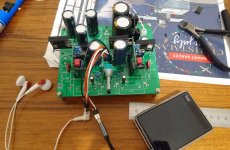
Initially had one of the filter caps sound the wrong way, power supply voltage kept dropping and current draw increasing, and I heard a sizzling. Pulled the plug before it burst, and seems like everything is fine after swapping that cap out. Also had to put larger heatsinks (than what's on them in the picture)on the mosfets - they got too toasty with the small ones.
Will probably change the input, output and pot connectors to dupont ones, think it'll look cleaner and be more stable. I'll get started on mounting it while waiting for the dupont connectors to arrive from China.
I think it's a notch too small, breaks the wire off (24awg)
I ended up using pliers just so I could get it done and try the amp.
Got it working now. Phew!
Initially had one of the filter caps sound the wrong way, power supply voltage kept dropping and current draw increasing, and I heard a sizzling. Pulled the plug before it burst, and seems like everything is fine after swapping that cap out. Also had to put larger heatsinks (than what's on them in the picture)on the mosfets - they got too toasty with the small ones.
Will probably change the input, output and pot connectors to dupont ones, think it'll look cleaner and be more stable. I'll get started on mounting it while waiting for the dupont connectors to arrive from China.
Attachments
Use the next larger crimp slot then? The amount of insulation that goes into the crimped is minimal - just enough for the two prongs to fold over and crimp the insulation part. The part that crimps the bare wire is very short - maybe 2mm max of bare wire. Too long and maybe it jams the connector genial opening. You may have it in backwards? Please post photo of how your crimp ferrule fits into fool before you squeeze.
This video may help.
YouTube
This video may help.
YouTube
Last edited:
The crimpers are excellent I have found, not a ratchet, just fine manual control that gives a great crimp.
The larger PA-20 is the one for these sizes, they ship straight from Japan -
NEW Engineer PA-20 Universal Mini Micro Crimping Tool Crimp With Free shipping 4989833035204 | eBay
The larger PA-20 is the one for these sizes, they ship straight from Japan -
NEW Engineer PA-20 Universal Mini Micro Crimping Tool Crimp With Free shipping 4989833035204 | eBay
Haven't tried crimping again yet, but I'll post a picture next time I get round to doing some crimps.
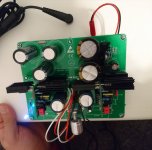
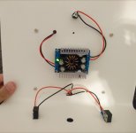
Mounted this one up, waiting on the dupont connectors for the pot, eventually it'll be occupying that hole between the headphone jacks. For now it has some pcb pins on its legs to extend them. Jst for power is temporary, will be a terminal block when I get some with the right pitch.
The mosfets on the daughterboards gets pretty toasty so ended up with the larger heatsinks on them.
3300u FC on outputs, but that may change.
This step up has a weird 3 stage whine on first power up so probably gonna swap it out later.
Attachments
I'm just building mine and have a few questions for X please...
- Is it necessary to increase C124/C134 to 1000uF as you have done in your HPA build?
Is this a good value to stick with for 32 ohm headphones as well? Any other changes beyond these caps and the parts listed at the end of the first post? Want to use the HPA version for headphones and as a pre into an ACA.
You want to look at the output coupling cap, C126/136. It needs to be large enough to give you the bass extension you need. Choose the bass extension you want, say 20Hz, then halve that twice (2 octaves) or 5Hz and choose that as the -3dB frequency to strive for using f=1/(2 pi R C) where R is impedance of your headphone. So for 32ohm and 5Hz, I get 1000uF. If you wanted to make sure it digs deep, 2200uF will work well too.
You want to look at the output coupling cap, C126/136. It needs to be large enough to give you the bass extension you need. Choose the bass extension you want, say 20Hz, then halve that twice (2 octaves) or 5Hz and choose that as the -3dB frequency to strive for using f=1/(2 pi R C) where R is impedance of your headphone. So for 32ohm and 5Hz, I get 1000uF. If you wanted to make sure it digs deep, 2200uF will work well too.
UKA1H222MHD Nichicon | Mouser
Will 2 of these do the job?
Yes, perfect.
Yes, perfect.
Thank you. All parts as I can figure have been ordered now. Stuff coming in from all over the world for this thing. Think I got it right but I am sure a few things are missed and regardless this will be a journey for me. I apologize in advance for the questions that will be coming from this neophyte.
Think I am ready to start soldering but before I do I would like to double check the part changes and ask one more question. First here are all the parts I have that differ from the pre-amp only version based on this thread. This is for a 12db gain Lender HPA/preamp running on 24v. Please let me know if I got it right.
Main Board
C126,C136 - 2200uf
Daughter Boards
R14 2k2
R15 11R
R10 4k7
Q4 TTA004B
Now here is my question. Can the gain be adjusted a bit lower? In the preamp thread it mentions increasing R11 to 2k2 to reduce gain to 14db. Would adjusting R11 reduce gain further in the HPA version as well?
Here is my situation. In my current setup I am using a Schiit Vali2 as a preamp for my ACA. With this I can choose between 2db and 14db gain. I find 14db gain too much, this will drive the amp to distortion before reaching full volume and is too loud for me to ever need. Most of the time I keep it on 2db gain and am happy at half to 3/4 volume. With my headphones I run an inline attenuator even on 2db gain and never need more. I feel 12db may still be too much but can live with it if going lower would compromise the Lender's performance.
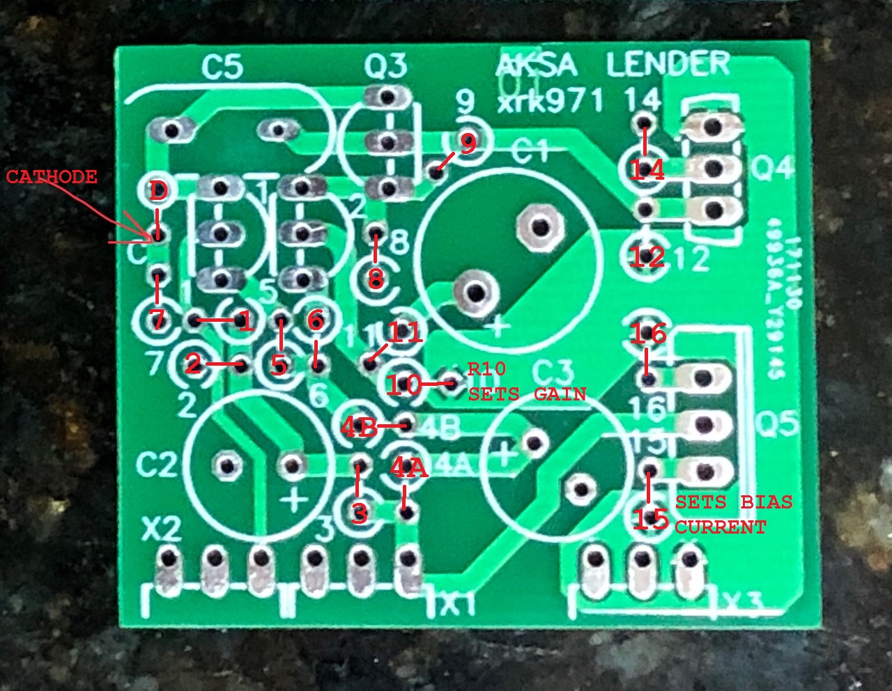
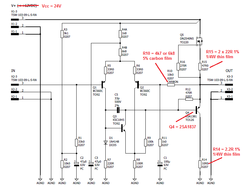
In the schematic below. the gain is set by R10 and R11 with the relation: Gain=(R10+R11)/R11. Let's pick for example R10=33k and R11 15k, then G=3.2x or 10dB. I picked 33k for R10 because actually, we want to run less feedback to the input stage and we want to match the input impedance of 33k presented by R1.
So give that a try.
R14 is 2.2R or 2R2 not 2k2 (2200ohm)!
I have not used TTA004B, but specs shows it should work - same pinout as KSA1381. Make sure you are not burning off more than 1.5w (and use a good heatsink). The Q4 will be running at about 1/2 vcc or 12v x 125mA bias is 1.5w. So don't exceed 125mA. make R15 (11ohms) bigger if too hot. About 75mA is plenty for most headphones and if driving low impedance 32ohm headphones, you might need the 100mA+ bias current.
Last edited:
In the schematic below. the gain is set by R10 and R11 with the relation: Gain=(R10+R11)/R11. Let's pick for example R10=33k and R11 15k, then G=3.2x or 10dB. I picked 33k for R10 because actually, we want to run less feedback to the input stage and we want to match the input impedance of 33k presented by R1.
So give that a try.
R14 is 2.2R or 2R2 not 2k2 (2200ohm)!
I have not used TTA004B, but specs shows it should work - same pinout as KSA1381. Make sure you are not burning off more than 1.5w (and use a good heatsink). The Q4 will be running at about 1/2 vcc or 12v x 125mA bias is 1.5w. So don't exceed 125mA. make R15 (11ohms) bigger if too hot. About 75mA is plenty for most headphones and if driving low impedance 32ohm headphones, you might need the 100mA+ bias current.
Thanks. I will do some noodling on that to make sure I understand what you are saying particularly around the bias. I did initially order a pair of 2SA1837s but had some doubts over their quality.
https://www.diyaudio.com/forums/parts/333400-toshiba-2sa1837.html#post5684656
Would these be a better way to go if they are acceptable?
- Status
- This old topic is closed. If you want to reopen this topic, contact a moderator using the "Report Post" button.
- Home
- Amplifiers
- Headphone Systems
- Aksa Lender HPA