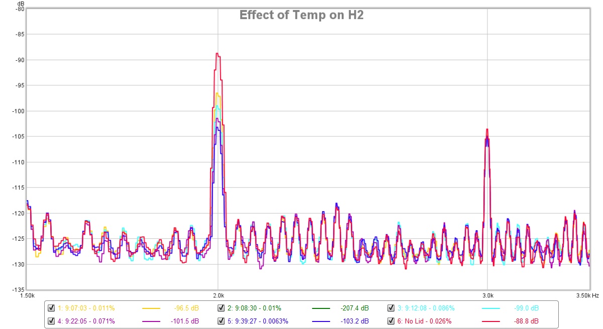
It's a temperature effect on probably the output 2SA1837 or maybe even the LTP? But I took several measurements over about 30 min after the lid wad replaced. The temp of the output BJT was 97C with cover on and 67C with cover off. It looks like only the second harmonic distortion is reduced at higher temperatures. Or it could be that temperatures inside the cover are more homogenized and the LTPs are closer together in temp. As they are not thermally bonded, they may have differences when the lid is off. It's definitely a thermal effect though. THD went from 0.026% with lid off to 0.0063% with it on. The relative balance of H2 and H3 will make it sound sweeter with the lid off and more analytical with lid on. Adjustment of the LTP degeneration resistor values and also the R9 (make 68k or even 50k) can raise relative level of H2 vs H3.
Attachments
Last edited:
Brilliant work, Vunce!
You could easily put the preamp into a box three times smaller!
Nice use of a SMPS and elegant wiring on the selector and sources.
Some very serious caps in there.......
I never expected this preamp would be so good, but the drive on the voltage amp is very fast and I think it helps with the very low THD. XRK has championed this circuit and added his own versatility to it.
Thanks to XRK, J-P, and Vunce for making it reality.
Hugh
Ok, you have uncovered one instability/dependancy, good work.It's a temperature effect.....
Dan.
I'm just building mine and have a few questions for X please...
- Is it necessary to increase C124/C134 to 1000uF as you have done in your HPA build?
- Is there any benefit from matching Q5s on the daughterboards?
- Should both C132 (or C1032) and C133 (or C1033) be installed? What are the options here?
- Should I build the CLC filter? I see it's not on your HPA build. If I use it would it affect the input voltage required?
Thanks
Antony
Last edited:
I'm just building mine and have a few questions for X please...
- Is it necessary to increase C124/C134 to 1000uF as you have done in your HPA build?
Yes, use as big of a value as you can fit here while still using a high quality brand (Elna Silmic II, Nichicon KA, Panasonic FG, etc). The values affects the bass extension depending on your phone impedance. For 50ohm phones, set the -3dB corner frequency to 2 octaves below where you want the amp to play bass flat to. Say you want flat to 20Hz, then 2 octaves below is 5Hz. Use equation Fc=1/(2 pi R C) and solve for C given impedance of phones in ohms and Fc of 5hz. So that gives 640uF. So 1000uF should be plenty.
- Is there any benefit from matching Q5s on the daughterboards?
Not really, as long as bias currents on both channels is within 5% you are fine.
- Should both C132 (or C1032) and C133 (or C1033) be installed? What are the options here?
It's your choice, but many people don't think a bypass cap on the inputs is a good idea as they say it smears the sound compared to even a plain electrolytic cap like an Elna Silmic II 10uF 35v cap. Use a high quality film cap here. Follow the same equation for setting the value. In this case, the input impedance is set by the 22k resistor to GND. So a 1uF cap here gives flat response to 29Hz. I have since changed this value to a 5.6uF film cap so my input bass extension is flat to 5Hz.
- Should I build the CLC filter? I see it's not on your HPA build. If I use it would it affect the input voltage required?
If you do not have a noise issue with the DC-DC converter adding noise to your amp, then not needed - however, it is a good idea to have it so that RF/EMI from the DC-DC converter in the amp gets radiated back out to your mains or environment outside of the box. I have used 47uF and 1mH here with a 51R parallel to the 1mH for stability.
Thanks
Antony
As the TH and SMT MELF and SMT 0805/1206 boards have different designators, let's assume you have the TH one, as that is assumed to be needed for the 2SA1837's to be used.
Main board (MB) schematic:
Last edited:
where does one get the 2SA1837 nowadays?
I had a look on ebay but I guess anything from china and surrounds are suspect. what about ones from the UK? (5X 2SA1837 High Frequency/HF/RF PNP Amplifier Transistor PACK OF 5 | eBay)
I had a look on ebay but I guess anything from china and surrounds are suspect. what about ones from the UK? (5X 2SA1837 High Frequency/HF/RF PNP Amplifier Transistor PACK OF 5 | eBay)
I bought the last remaining batch of genuine Toshiba from Mouser a year ago. They are becoming rare... I can sell you one when you order the Aksa Lender pre MB's. 2SA1837 are $10/pair.where does one get the 2SA1837 nowadays?
The photo in that link is all wrong. The 2SA1837 are all black epoxy covered, no metal tab.
I bought the last remaining batch of genuine Toshiba from Mouser a year ago. They are becoming rare... I can sell you one when you order the Aksa Lender pre MB's. 2SA1837 are $10/pair.
The photo in that link is all wrong. The 2SA1837 are all black epoxy covered, no metal tab.
You could try 2SA1837LB-TF3T at 2SA1837LB-TF3T - Power Transistor -230V -1A
")
just pulled together a cart for bits for this build
looking at the schematic I had a question - the cap mx portion has a zener in this design but not the DCA - why the difference?
There’s no zener on this design. Just a 1n400x like on DCA. Show me where there is a zener.
Connector is special 8 pin through hole ribbon connector. Special part discussed in main preamp gB thread.
cool - had a look through the main thread as pre-reading haha I like the PCB connectors for X121
Gonna finalize my parts order and then order some boards!
Although without any mounting I doubt I can use it - the DCA I build it just sitting there as its too cumbersome to use while sitting on a beanbag etc...and worried about static from the carpet! Will have to wait to mount it up before being able to really listen
whats the dimensions of the mainboard? (so i can order another bit of acrylic)
From post #1 from GB thread: 155mm x 157mm for main board.
AKSA's Lender Preamp with 40Vpp Ouput GB
- Status
- This old topic is closed. If you want to reopen this topic, contact a moderator using the "Report Post" button.
- Home
- Amplifiers
- Headphone Systems
- Aksa Lender HPA