Firstly this is not (and will not be) a project. It is just a publication.
So build at own risk.
It is well know that we do not use tubes and coupling caps.
But that does not stop us from admiring John Broskie's numerous brilliant ideas from time to time.
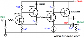
Recently he posed this Super-Simple, Super-Fine FET Circuit :
Designing with FETs
It is actually simpler than some two-transistor, single-rail, single-ended headphone amps that can be found in the forum or the net.
And if you would mirror the Broskie circuit about the Gnd line, and replace the lower half with complementary devices,
you would actually actually end up with Nelson's F5 topology.
Interesting !
But the Broskie circuit as shown only has 5mA bias at the output stage. So it is not much driving anything lower than <10k.
Could it be configured to work as a HPA with decent performance, namely better than -80dB at 1Vrms into 30R ?
Also, for it to be able to swing enough voltage and current, supply voltage should be 30V, and output bias 150mA.
And gain should be about 10, just like most of our other HPA’s.
Patrick
So build at own risk.
It is well know that we do not use tubes and coupling caps.
But that does not stop us from admiring John Broskie's numerous brilliant ideas from time to time.
Recently he posed this Super-Simple, Super-Fine FET Circuit :
Designing with FETs
It is actually simpler than some two-transistor, single-rail, single-ended headphone amps that can be found in the forum or the net.
And if you would mirror the Broskie circuit about the Gnd line, and replace the lower half with complementary devices,
you would actually actually end up with Nelson's F5 topology.
Interesting !
But the Broskie circuit as shown only has 5mA bias at the output stage. So it is not much driving anything lower than <10k.
Could it be configured to work as a HPA with decent performance, namely better than -80dB at 1Vrms into 30R ?
Also, for it to be able to swing enough voltage and current, supply voltage should be 30V, and output bias 150mA.
And gain should be about 10, just like most of our other HPA’s.
Patrick
Last edited:
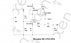
With 30V rail, the output DC should be about 15V, and the 9:1 feedback network means that the JFET source is at +1.5V. Most of the low-noise, high-Yfs JFETs used in other amplifier circuits would be left with no bias at Vgs -1.5V. In the end, the J111 series came to the rescue. They are quite low-noise, have decent transconductance, and yet has very high Idss, making them ideal when used with large negative Vgs.
But there is still not much open loop gain to drive 30R load, and the feedback network itself is also not a light load to drive in addition. So the JFET drain resistor has to be replaced with a E452 CRD (Current Regulating Diode), to recover some OLG. One can of course also use a 2SK209GR with 4~5mA Idss instead. The latter costs a lot less and is even lower noise.
But a practical CCS needs voltage headroom, so a emitter resistor is added to raise the 0.6V Vbe of the PNP to something like 1.5V, to prevent the CCS from being totally starved of Vds.
Distortion is in the order of 70~80dB with 30R load at 1kHz 1Vrms. But if you happen to hit a sweet spot, like we did here with 30R load, 5mA CCS and 6R emitter resistor, you can go almost one order of magnitude lower, due to 2nd harmonics cancellation. But this condition depends on a whole bunch of circuit parameters. If you change one, you get off the sweet spot straight away. Not very practical for a product, but still of interest for DIY.
Frequency response is very clean, as the output is already quite heavily loaded by the feedback network, even without the phone. Bandwidth is over 1MHz. But you will need minimum 470μF decoupling cap for 30R load to have decent LF cut-off.
And we have only added one CRD compared to the original Broskie.
Patrick
.
Attachments
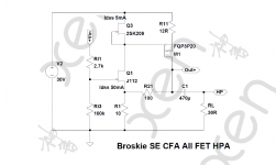
Can we also make it work with MOSFETs as in the F5-HA ?
Yes we can, thanks to the CCS drain load.
THD Performance is a few dB worse than using the PNP, as one would expect because of the lower gm.
But one can still find a sweet spot for 2nd harmonics cancellation as before.
Patrick
.
Yes we can, thanks to the CCS drain load.
THD Performance is a few dB worse than using the PNP, as one would expect because of the lower gm.
But one can still find a sweet spot for 2nd harmonics cancellation as before.
Patrick
.
Attachments
With 30V rail, the output DC should be about 15V...
Only for infinite load.
With any lower load, you can pull-up 15V but pull-down only as much as the resistor will pull. For 150r load, +15V and -7.5V swing. For 30r load, +15V and -2.5V swing.
If you know your load, pick RC as 1.4X the load and bias the transistor to drop 29% of the supply voltage.
For 30r-600r load range, we can't optimize for all. Some more thought needed. We don't want +/-15V in 30r (over 3 Watts!). We do want over +/-10V in some hi-Z phones. I believe the attached plan will drive well into almost any headphone. +9V/-3.6V in 32r (0.2W), +9V/-7V in 75r (0.3W), +9V/-9V in 108r (0.36W) and up (0.13W in 300r).
I do not know how to pick a JFET to bias it up for 2.1V at the NFB node. In DIY we can trim "1.2K" 2X up or down to seek a bias; much more deviation suggests grabbing a different FET.
I have done essentially this (with a different input stage) and it worked very-OK for output in a collection of 'phones.
As you say, the residual is pure single-ended. The final device of a resistor-loaded "Power" stage works VERY hard, from over 2X current right down to cut-off.
Attachments
WOW! This circuit should be right up 'ole XRK971's alley since he's soooo in to HAs circuits which use big ole' nasty, electrolytic coupling caps in series with the output(s).
I avoid such circuits like the plague and stick with only DC-coupled outputs even if a servo is used.
Thanks for posting Patrick & Merry Christmas!
I avoid such circuits like the plague and stick with only DC-coupled outputs even if a servo is used.
Thanks for posting Patrick & Merry Christmas!
The circuits posted will work as intended with any RL (after the cap) between 30R and 600R, according to Spice.
Also according to Spice, and with the CCS drain load, there is no real advantage in using a Darlington or CFP.
But do feel free to play around with other combinations.
They cost nothing in Spice.
Cheers,
Patrick
Also according to Spice, and with the CCS drain load, there is no real advantage in using a Darlington or CFP.
But do feel free to play around with other combinations.
They cost nothing in Spice.
Cheers,
Patrick
> I avoid such circuits .... and stick with only DC-coupled outputs even if a servo is used.
+1. But then people also like MacDonald's.
And we should all celebrate that we have a free choice.
It drew my interest largely because of its similarity to a top-half-only F5.
Patrick
+1. But then people also like MacDonald's.
And we should all celebrate that we have a free choice.
It drew my interest largely because of its similarity to a top-half-only F5.
Patrick
Last edited:
Broskie ZGF, or FET Aikido HPA
There is another circuit on the same webpage as listed in post #1 that I find very interesting. Namely the FET Aikido.
Again it is primarily meant to be a line amp that drives high impedance load.
So it took some effort to get it to work for headphones.
But with the right choice of devices, the performance is actually quite good.
Apart from the simplicity and good PSRR (depends on Yfs match of the output devices), it is thermally self-stabilising.
The bias current is in the -ve tempco reason of the lateral MOSFETs, as in the UTHAiM.
So no real danger of thermal runaway.
AND it has Zero Global Feedback.
If I have had to build a single-rail circuit, this would be one of the candidates.
If only there are 1000µF MKP caps that are not huge and cost a fortunate ........
Patrick
.
Attachments
Isn't that rather similar to the above, except that the first stage is low current and gain only (with NFB) ?
And that followed by a Sziklai follower outside the NFB loop.
The only advantage is that it is less load-impedance dependent.
But the ones above can drive 32R anyhow.
So also no problems for 300R, etc.
Patrick
And that followed by a Sziklai follower outside the NFB loop.
The only advantage is that it is less load-impedance dependent.
But the ones above can drive 32R anyhow.
So also no problems for 300R, etc.
Patrick
- Status
- This old topic is closed. If you want to reopen this topic, contact a moderator using the "Report Post" button.
- Home
- Amplifiers
- Headphone Systems
- The Tubecad Super-Simple, Super-Fine FET Circuit in HPA Configuartion