Some issues
Well, I got it all put together, but have a couple of issues.
I am using a shunt regulator from K&K audio for each of the output tubes to get my regulated 220v @ 40ma (20 for the regulator and 20 for the 71a tube), and I have a string of VR tubes to get the 180v I need for the 56 tubes (one string for both tubes).
My isssue is with the left channel; I cant get the shunt regulator to adjust to 220v without increasing the current ~6ma. The right channel measures fine both current and voltage.
The second issue is that there is hum (does not increase with volume), which is also on the left channel. I have checked all my grounds and component orientation (on the shunt board) and everything looks good. I am thinking something on the board, but not sure which component to look at first.
The right side is perfect and sounds great
It also hums on the left side with no input connected and driver tubes removed. The music does sound good (really good), but I cant live with that hummmmmmm on the left side, any ideas?
I checked the voltage and it is 4.95 vdc.
I am going to go ahead and replace the shunt mosfet (IRF810) and the corresponding voltage resistors on the shunt reg board. The kit uses a lot of carbon comp resistors, which I dont like, maybe a few have drifted?
I also forgot to mention that I have the power supply in a seperate chassis.
I will double check all my grounds when I get off work and post a pic of the build.
Filaments are DC. I do notice that the filament wires are really close to the 56 plate chokes...I may have to reroute them. The chassis is really tight as all the filament supplies and shurnt reg supplies take up the bulk of the space.
Also, the filament transformers are in the power supply chassis and the regulators are in the main amp chassis; the umbilical is not shielded, not sure if this is a necessity or not as the right side is quiet? Each 71a has its own supply and the 56 shares a 5vdc series connected supply.
I am really starting to wonder is I should have just wired in a string of vr tubes for each output tube instead of the K&K shunt modules (mainly for the glow and simplicity), which would have saved me a lot of real estate.
Last edited:
I recommend reading Heater Wiring - the Good the Bad and the Ugly
Do you share B+ for both channels or do you have two?
Do you share DC heaters regulator for both channels or do you have two regulators?
Do you share B+ for both channels or do you have two?
Do you share DC heaters regulator for both channels or do you have two regulators?
Last edited:
B+ is shared but each output tube has its own shunt regulator. The output tubes each have thier own DC filament supply and the driver tubes share a series connected DC supply
I still dont understand why I could not adjust my regulated voltage on the left side to 220v without increasing the current.
I still dont understand why I could not adjust my regulated voltage on the left side to 220v without increasing the current.
Last edited:
easy hum source check- listen to output, and shutdown one at time: (on secondary ~ side, be careful!)
(amp with shorted inputs)
* HV supply
* heater circuits one by one
* if no changes, then put far away power trafo (or shut down whole trafo and listen)
powersupply capacity will keep playing for a second(s), enough to listen if hum stopped.
1 actually, i have hum present ,if heater dc is floating-not grounded by one side
2 not grounding input trafos shields and core makes hum sensitivity too
-----------------------
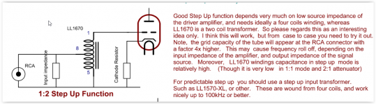
step up idea-- grid choke this way should be driven by low impedance; my gyrator scheme in page 2 will fit.
60€ a pop....
http://www.lundahl.se/wp-content/uploads/datasheets/1670.pdf
(amp with shorted inputs)
* HV supply
* heater circuits one by one
* if no changes, then put far away power trafo (or shut down whole trafo and listen)
powersupply capacity will keep playing for a second(s), enough to listen if hum stopped.
1 actually, i have hum present ,if heater dc is floating-not grounded by one side
2 not grounding input trafos shields and core makes hum sensitivity too
-----------------------
step up idea-- grid choke this way should be driven by low impedance; my gyrator scheme in page 2 will fit.
60€ a pop....
http://www.lundahl.se/wp-content/uploads/datasheets/1670.pdf
Attachments
Last edited:
OK, I think I may know what the issue is. So, I removed the shunt regulators and added a dropping resistor for the output tubes and I now have low level hum in both channels. I think the one regulator was bad and not regulating and the other that was working had no hum. So, now I think this is a matter of needing more power supply filtration.
I currently have LC (16H > 40uf), which is not enough now, but was enough with the regulators. I am going to add another choke and a lot more capacitance and see if this helps. It sounds like 120hz hum. Would it be wise to add a little capacitance in the amp chassis, maybe 4uf at the jack?
Also, I dont think I originally had enough voltage going to the regulators as my B+ was 230v and I only needed to drop 10v.
according to his scheme, it should be ok to unplug driver tubes, and listen 4 hum.
With driver tubes removed, I still have hum.
Not sure if it makes a difference but my OPT secondaries are not grounded.
Also, I have 60hz hum (I think), not 120hz as I said above. The hum is too rounded to be 120hz.
Last edited:
- Home
- Amplifiers
- Headphone Systems
- Lundahl LL2765 Headphone Amp Project