That will greatly increase the supply impedance compared to the regulated supply. It will also result in worse filtering, in particular when the parasitics of the supply caps are factored in.
Hi, Tom!
Yes.
But caps will be a real reservoir of the energy, not a “feedback’ed ventile on the pipe”.
[emoji6]
If we would be in need for a best possible supply - than shunt regulation must be applied. Something like this will be good enough:

But this circuit likely not need this.
Just place something like 4700 uF + 10 Ohm + 1000 uF (latter should be decoupled with small sized 100/47 uF and good > 100nF NP0).
As for inverting vs non-inverting: I'm assuming you're concerned about common-mode distortion. That's not really a thing anymore with modern opamps. I'm sure you can find one opamp out there somewhere that shows common-mode distortion, but amps like the LME49710, OPA1611, etc. perform better non-inverting than inverting, at least for buffer applications, due to the 6 dB higher loop gain of the non-inverting configuration.
Yes, you are mostly right!
Common mode distortion are nonlinear to the common-mode itself.
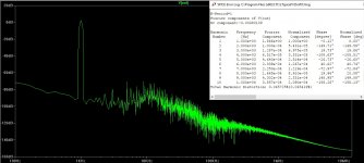
But next i want to have as deep as possible feedback depth at least up to third harmonic of the 20 kHz.
And there is no chance to override THS4021 with one chip at this task:

OPA1611 for compare:

And, of course, we can afford 6 dB drop there.
Simultaneously, we need to concern about HF common mode error. Just check:

At 10 MHz range there are a good receiving antenn is present - headphone cable.
So, we must go for balanced 4-wire headphones with splitted ground, or use somethind like Murata 78602/2c choke.
Last edited:
What are your sources?
Use just the MosFet; no input-op: build an amp, not a buffer -sounds much better than op and buffer.
Use just one psu für both channels -or connect the psus later;-)
Build a p-channel-MosFet-amp. Sounds a little bit cleaner and clearer.
For the now residual 4 or 5 e-parts you do not need a board, a "sound-destroyer"-)
...
LG
I don't know why you would want +/-15V and 200mA for any headphone.
There's a very useful table of headphone characteristics (HERE).
According to that table, the headphones that need the biggest voltage swing are (a) low sensitivity, and also (b) high impedance.
The "winner" (largest required voltage swing of them all) is the Beyerdynamic DT770 Pro, with a sensitivity of 98 dB SPL @ 1V, and an impedance of 251 ohms. They require a voltage of 3.981 volts RMS to reach the target SPL which 110dB. That's plus or minus 5.63 volts, peak to peak. If the amplifier's maximum undistorted output voltage is 7V less than the rails, you'd want a power supply of +/- 12.6 volts. {7V might not be enough if using a MOSFET output stage}
Also according to that table, the headphones that require the biggest current to achieve the 110dB target SPL, are weirdo outliers made by Hifiman. The HE-4 requires 159mA and the HE-6 requires 261mA. If we ignore/discard those, then the headphones with the third biggest current requirement are the Fostex TH-900: 63.4 mA RMS, per channel. Input impedance is 25 ohms and sensitivity is 108 dB SPL @ 1V input.
To summarize: +/- 13V supplies at 150 mA, will let you drive all but two of the headphones in that table. It is probably a good idea to include big filter capacitors that let you ride out the difference between RMS and peak, when delivering a full amplitude 20 Hz sinewave.
You all have to modify the/your "reference-headphones". They all sound very ugly - capsules to big, suspension, cables ... all;-P
The most headhones do "win" per ADDITION of "rough and dull" sound, per separate headhoneamps: these counter the diffuse and noisy and gray headphone-sound;-)
The most headhones do "win" per ADDITION of "rough and dull" sound, per separate headhoneamps: these counter the diffuse and noisy and gray headphone-sound;-)
But this circuit likely not need this.
Just place something like 4700 uF + 10 Ohm + 1000 uF (latter should be decoupled with small sized 100/47 uF and good > 100nF NP0).
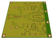
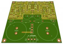
I have C-R-C on the pcb before the voltage regulators
First C: up to 10,000uF
Resistors: pitch 18mm for each channel
Second C: up to 1,000uF for each channel
If you have a volume pot soldered to the input of the amp board, the volume pot will drain the cap.
Tom
Thanks for your reply.
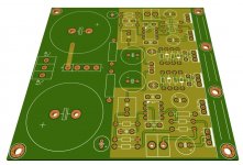
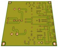
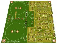
Layout based on the circuit in post 17.
Removed one set of voltage regulators, now there is one set of regulators for both channels.
Looks great
 ! What is the part number of the heatsink you're using?
Looks great
It's this one: SK 68, Extruded heatsinks for PCB mounting, Heatsinks f.cool, Fischer Elektronik
100mm length
")
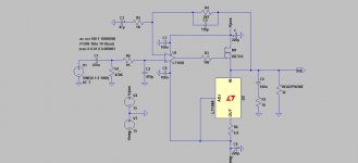
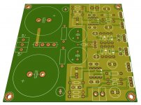
Why do you need C3 and R5?
Power supply is C-R-C (C1-R1-C3 and C2-R2-C4) feeding into the voltage regulators.
R5 is for setting the voltage for the LM317 (Q1) together with R3
R6 is for setting the voltage for the LM337 (Q2) together with R4
- Status
- This old topic is closed. If you want to reopen this topic, contact a moderator using the "Report Post" button.
- Home
- Amplifiers
- Headphone Systems
- Mosfet class A headphone amplifier