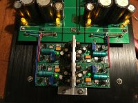
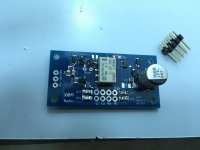
Very pleased with the build so far, the regulator wiring is perfectly straight forward and neat. The TeddyRegs are excellent to be fair, rock solid 15.08V on each, I did a decent job on those at least.
The rear solder turrets on the motherboard have been connected with solid wire as a bus bar - all signal 0V's will return to this bar. They will be the only wires to cross the regs and will fly down the middle running along the T-bar heatsink.
Patrick, I think I can run all signal around the regs completely, in a tidy manner. Hopefully show you later. Fingers crossed no 50Hz hum. The input 0V's are also solid wire down the middle, the input signal wires will pass down the side and over the pot to the Xfeed. I'll try and use Van Damme shielded cable for the input at least. All 0V's from the SHPP and output jack will go to the bus bar.
Not sure what else to tell you right now but she's looking good
BadBoyGolf asked which chassis I have used, it is this one from ebay, tailor made for this motherboard if you wanted heatsinks. -
Class A Aluminum Case/Preamp box/ Amplifier Enclosure/ Mini Amp Chassis HIFI Box | eBay
Now there is no hole for headphone Jack, just for a small power button. So you will need a 24V drill or one with lots of torque and a step hole drill to suit your phone jack. Neutrik D shell is around 24mm so open up the button hole and for me, I will use a switch on the back panel... I forgot to make a hole for an front panel LED actually.
3PC LARGE HSS STEP CONE DRILL TITANIUM BIT SET HOLE CUTTER + STORAGE POUCH | eBay
Coffee and eggs for me now...")
The rear solder turrets on the motherboard have been connected with solid wire as a bus bar - all signal 0V's will return to this bar. They will be the only wires to cross the regs and will fly down the middle running along the T-bar heatsink.
Patrick, I think I can run all signal around the regs completely, in a tidy manner. Hopefully show you later. Fingers crossed no 50Hz hum. The input 0V's are also solid wire down the middle, the input signal wires will pass down the side and over the pot to the Xfeed. I'll try and use Van Damme shielded cable for the input at least. All 0V's from the SHPP and output jack will go to the bus bar.
Not sure what else to tell you right now but she's looking good
BadBoyGolf asked which chassis I have used, it is this one from ebay, tailor made for this motherboard if you wanted heatsinks. -
Class A Aluminum Case/Preamp box/ Amplifier Enclosure/ Mini Amp Chassis HIFI Box | eBay
Now there is no hole for headphone Jack, just for a small power button. So you will need a 24V drill or one with lots of torque and a step hole drill to suit your phone jack. Neutrik D shell is around 24mm so open up the button hole and for me, I will use a switch on the back panel... I forgot to make a hole for an front panel LED actually.
3PC LARGE HSS STEP CONE DRILL TITANIUM BIT SET HOLE CUTTER + STORAGE POUCH | eBay
Coffee and eggs for me now...
Attachments
Last edited:
Ok last entry today, I need to build the SHPP.
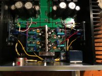
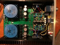
Just to show Patrick that hopefully the signal wires will avoid crossing the regs. Once things are soldered and cable tied nicely, we should be in business.
The SHPP is powered directly from the motherboard 15V outputs, wires run under the regs.
Connecting the outputs from the under the pot is slightly awkward, pads for pins at the rear of the pot would be better I feel. I may use pluggable Molex type connectors for the SHPP.
Attachments
The case is just a standard Breeze Audio 2107, like the one we used.
Douk Audio Universal Chassis Aluminum Box Amplifier Enclosure Verstarker Gehause | eBay
Patrick
Douk Audio Universal Chassis Aluminum Box Amplifier Enclosure Verstarker Gehause | eBay
Patrick
As I already said, the input wires from the X'feed will be n-times shorter
and much further away from any power supply lines
if you place the ampboards in the middle, especially with the input facing the front.
But it is your build, so as long as you are happy with it, it is the most important.
I only made the comment for others who might wish to consider similar layout.
They may also look at the Super Linear Current Amp thread for another layout using non-SMD X'feed.
The pot was placed as close to the X'Feed as possible, using shaft extension.
https://www.diyaudio.com/forums/hea...r-transconductance-amplifier.html#post5569028
Cheers,
Patrick
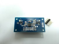
For the sake that it might be of some help to someone when they start, here is my SHPP board finally. I neglected to order zero ohm chips for some reason but they are on the way...
So I would advise the GB members when ordering the SHPP BoM to get 0805 size parts in place of 1206 parts specified. The PDF does mention going down one size but you will be ok with 0805 for all components.
The cluster around the op-amp is tight, work your way outwards and solder the central pads first. Tin one pad, apply liquid flux and slide the component in as you apply heat. Then adjust making sure they cover both pads equally.
Double check LED and diode orientation every time, the markings are hard to see both on the board and the parts themselves.
This SHPP board is possibly one of the most challenging SMD assemblies I have done, but I enjoy that. Get a good loupe or magnifying glass and check every solder joint each time. I fought a while with a solder bridge across R13 and C3, only to see that they are connected anyway... Using continuity test is a good way to check things.
As a glimpse into my mind, R5 on the right side first pic is killing me, all skewed and that. I hate it, it's bound to effect sound quality... we'll see. This is one of my messier jobs really looking at the pics but If I don't think about it I'll be ok
Attachments
Last edited:
Before downsizing, you should check capacitors has sufficient headroom in voltage rating, and resistors will take the power.
For example R20, and the input filtering caps to the opamp.
Do not forget that X7R capacitors loses > 50% of their capacitance when they see a DC voltage close to their rating.
You will find lots of information on the net.
Patrick
For example R20, and the input filtering caps to the opamp.
Do not forget that X7R capacitors loses > 50% of their capacitance when they see a DC voltage close to their rating.
You will find lots of information on the net.
Patrick
Out of interest Patrick is there any issue (other than cost) with using higher quality 35v Tantalum caps for C1,2, 11,12?
https://www.mouser.co.uk/ProductDet...Z1n0r9vR22fixilZl6Mr8uyeasmoeRjw8uWe0t90lBQ==
https://www.mouser.co.uk/ProductDet...Z1n0r9vR22fixilZl6Mr8uyeasmoeRjw8uWe0t90lBQ==
I have PMs asking for PCBs.
Here you can join the 3rd GB :
Interest for 3rd GB for Pioneer Super Linear Headphone Amplifier
Patrick
Here you can join the 3rd GB :
Interest for 3rd GB for Pioneer Super Linear Headphone Amplifier
Patrick
You only trim one, depending on whether the offset is positive or negative.
And you do not need to use trimpots. I use fixed SMD resistors all the time.
You do need a collection / album.
I think Morde mentioned this also somewhere early in the thread ?
Patrick
I think it is mentioned in post #103: The Pioneer Super Linear Circuit
First Build Questions
A couple of questions from an amp building newbie:
Up until now my most complex amplifier build has been a Beta22. While it has a fairly high parts count the build steps are mostly spoon fed.
In reading through the Super Linear thread / BOM / PDF documentation I’m realizing this one is going to take a little more learning along the way.
I’ve started by ordering the parts for the regs, which I don’t think i’ll have too much trouble with. I’m planning the amplifier parts orders and reading through the forum and documentation and a few questions have come up:
-I see quite a few mentions of 150ma bias - how do I set the bias / measure values to confirm?
-As far as matching, I’m not shooting for the moon - I’ve only got a DMM and don’t expect greatness. Are the most important components to match the 2SA1312BL / 3324BL? Are there any other components that absolutely have to be matched?
-Is there anything on the boards I should confirm prior to applying power to hopefully avoid letting
the smoke out?
Thanks in advance!
- Home
- Amplifiers
- Headphone Systems
- The Pioneer Super Linear Circuit